Is there a formula or calculator to figure out the optimal placement of single or dual ports on a ported box?
Andrew Jones mentions it while unpacking his latest design

The idea is to place them such so the enclosure's internal standing waves are cancelled out at the farfield. Does it mean two ports are necessary? Can someone help with this or provide tips?
Andrew Jones mentions it while unpacking his latest design
The idea is to place them such so the enclosure's internal standing waves are cancelled out at the farfield. Does it mean two ports are necessary? Can someone help with this or provide tips?
There are standing waves in the box, between every two opposite boundaries (and perhaps some complex ones, but lets keep it simple). If inlet of a port is at pressure node of a standing wave, the sound likes to leak out like he says.
Usually a speaker box has some damping material in it, which is more effective the shorter the wavelength, hence standing waves are less problematic the higher the frequency, the higher the harmonic, right. Also woofer is low passed at some point and out of band wouldn't get excited that much either.
So, most problematic modes are the lowest ones and especially for the longest dimension, which is usually height. Lets consider modes of height of the box. Perhaps two or three first 1/2wl, 1wl, 3/2wl would be the most problematic. Pressure nodes of these are at the boundaries, and then 1/2wl doesn't have any more, 1wl has one pressure nor middle of the box, third harmonic or 3/2wl has two pressure nodes in the box, at 1/3 height of the box. And so on.
So, the ports should be located so their inlet is not center of the box, 1/2 height, nor 1/3 height of the box but some where else. Perhaps reasonable compromise is to have them somewhere 1/4wl height or so not to leak much the lowest most problematic standing waves, or harmonics.
I think AJ system probably works just fine. On a small box its hard to position the inlets so that they wouldn't leak some sound, especially on a two way box who have quite much harmonics on the pass band. The opposite phase thing as he says would happen for example on the third harmonic, whose two nodes 1/3 height of the box are out of phase each other. If the ports leak this, they would probably cancel out some. Not sure how big of a problem it was in the first place but if there is reason for two ports it would be logical to position them like so.
Its possible to make three way speaker that doesn't have such issue, size the box so there is no standing waves in the pass band. Or just make enough cone area for the low frequency system so that no porting is even needed, a fine option for home use.
Also, the damping might be enough to have low enough "leakage" from the port to not make it a problem. There are some rules of thumb, like the "leakage" should/could be ~-15db of the Helmholtz peak which we are after. Leakage could be very bad as well, like as loud as the Helmholtz resonance, or even louder. Also the port could have pipe modes happening, if long enough. All we want from the port is the Helmholz resonance and any extra noises including the leaks, pipe resonance and schuffing / wind noises are basically distortion, stuff we don't want, and should be minimized if one is after good performance.
Last edited:
Golden ratio. So located about 62% down the longest dimension of the box.
Alternatively, any pair of ports arranged asymmetrically along the longest dimension of the box should be pretty damn good.
Also consider the same effect occurs due to the placement of the woofer/driver, so having multiple woofers also helps.
Alternatively, any pair of ports arranged asymmetrically along the longest dimension of the box should be pretty damn good.
Also consider the same effect occurs due to the placement of the woofer/driver, so having multiple woofers also helps.
Yes, for example single woofer middle of dimension basically prevents the lowest mode happening on that dimension, something AJ seems to be utilizing with the speaker in question. Not sure if he mentions this on the video? With two woofers symmetrically placed would also have acoustic center of the dimension as well.
So, woofer on the middle handles 1st harmonic, ports not in the middle reduces leakage of 2nd harmonic to minimum, using two ports symmetrically negates at least some of 3rd harmonic leakage, rest is probably less offensive anyway and affected by damping material. Very fine solution for such speaker concept I think, ported two way speaker.
So, woofer on the middle handles 1st harmonic, ports not in the middle reduces leakage of 2nd harmonic to minimum, using two ports symmetrically negates at least some of 3rd harmonic leakage, rest is probably less offensive anyway and affected by damping material. Very fine solution for such speaker concept I think, ported two way speaker.
Last edited:
Hornresp or similar TL/horn software.Is there a formula or calculator to figure out the optimal placement of single or dual ports on a ported box?
The idea is to place them such so the enclosure's internal standing waves are cancelled out at the farfield. Does it mean two ports are necessary? Can someone help with this or provide tips?
IME until the aspect ratio is fairly high the box's air mass plug is presumed to be a uniform particle density, so no eigenmodes with an optimal driver location at L (i.d.) * 0.42 and the vent ideally 3r from any boundary (i.d.).
Boxes are 1/4 WL pipe resonators, so ideally we want the driver, vent at an odd harmonic and due to the lossy nature by venting it these points shift downward a bit, so for the driver: L (i.d.) * 0 (top), 0.217, 0.349, 0.424, 0.561 and the vent: 0.651, 0.714, 0.848, 0 (bottom)
Once eigenmodes are long enough it impacts vent performance via mass loading (begins to shorten it or make it larger if just a cutout).
His cab doesn't look nearly high enough aspect ratio to do this plus 'sounds' like one vent is in an even order harmonic (null), one in an odd order (peak), so on average assume it just damps the vent system, so his description while technically correct, 'sounds' like a bit of marketing BS to me; so no, you don't need two vents even if it was a truly high aspect ratio, which will do the same to a single vent.
In short, maybe it's a novel way to shrink a MLTL, though personally would just critically damp the vent.

Yeah, and for "ultimate" home hifi system I would argue one has to make bass solution that deals with room modes somehow, either some kind of open baffle / cardioid stuff trying to help some or separate multisub system or combination of. Ports are not needed elsewhere than on the subs (on wooferbox that handles the lowest bandwidth ), if even there because ideally there is many and big enough subs and thus possibly loud enough without ports. So, vents are just problem of non-ideal home hifi systems 😉 or, perhaps not a problem but a feature and associated set of compromises that need to be dealt with as good as feasible.
I took his explanation to mean placing the ports at 1/4 ID, so they are both addressing the same mode, but the phase is opposite at the two points, so the sound emitted for that mode cancels out in the far field.
Hi,
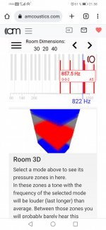
check out this graph to imagine it

I've traced the 3rd and 4th harmonic. These have pressure nodes 1/3 and 1/4 of the dimension where the ports are roughly located. In order for the port leakage to cancel out they would need to be opposite phase I think. If you follow the red marker line you'll see 3rd harmonic wave being opposite phase on the nodes where ports would roughly locate, while 4th harmonic have them in phase. But I could imagine this all wrong, as its standing wave sound is going both ways which is the definition for standing wave, there is time involved and so on. Perhaps its enough just to have them ports symmetrical for some cancellation happen. Perhaps he just slapped them there roughly and the performance is good enough so not too important where they are at as long as not at the walls and symmetric, or something. After all the leakage should be less if they are not exactly at the nodes. Perhaps its best to have them right there that takes account more things I'm able to fathom 🙂
check out this graph to imagine it
I've traced the 3rd and 4th harmonic. These have pressure nodes 1/3 and 1/4 of the dimension where the ports are roughly located. In order for the port leakage to cancel out they would need to be opposite phase I think. If you follow the red marker line you'll see 3rd harmonic wave being opposite phase on the nodes where ports would roughly locate, while 4th harmonic have them in phase. But I could imagine this all wrong, as its standing wave sound is going both ways which is the definition for standing wave, there is time involved and so on. Perhaps its enough just to have them ports symmetrical for some cancellation happen. Perhaps he just slapped them there roughly and the performance is good enough so not too important where they are at as long as not at the walls and symmetric, or something. After all the leakage should be less if they are not exactly at the nodes. Perhaps its best to have them right there that takes account more things I'm able to fathom 🙂
Last edited:
With larger diameter LF drivers, there can be an issue with cone rocking modes if dynamic air load isn't evenly distributed across the cone surface, and usually becomes an issue with slightly higher vent tuning frequencies ie pro audio applications. I see alot of pro designs with severe box standing wave modes, especially when the port is integrated with the enclosure wall. The solution to control cone rocking modes would usually be symmetrical port placement in relation to the LF driver and box length, but that can aggravate standing wave mode leakage from the port(s). So how would be the best (compromise) way to keep the dynamic air load on a larger cone driver even (ideally requiring symmetrical port placement in relation to driver on baffle) while still taking advantage of asymmetric port placement (to reduce cabinet modes in the far field)?
why people are talking of the 2x the WL of the longest internal panels distance as the main (spl) resonance peak to tame ? And then put the ports rigth at the middle of the enclosure heigth ? Bad understanding ? I also see elswhere for taming at best the internal resonance than the center of the cone should be at 1/3 of the enclosure botom or top heigth and the port(s) at 1/5 of the opposite panel on the front baffle (fbtw front best than back side)?
I think you right regarding those two modes, but looking at the mode above those, I think he is doing this:Hi,
check out this graph to imagine it
View attachment 1108403
I've traced the 3rd and 4th harmonic. These have pressure nodes 1/3 and 1/4 of the dimension where the ports are roughly located. In order for the port leakage to cancel out they would need to be opposite phase I think. If you follow the red marker line you'll see 3rd harmonic wave being opposite phase on the nodes where ports would roughly locate, while 4th harmonic have them in phase. But I could imagine this all wrong, as its standing wave sound is going both ways which is the definition for standing wave, there is time involved and so on. Perhaps its enough just to have them ports symmetrical for some cancellation happen. Perhaps he just slapped them there roughly and the performance is good enough so not too important where they are at as long as not at the walls and symmetric, or something. After all the leakage should be less if they are not exactly at the nodes. Perhaps its best to have them right there that takes account more things I'm able to fathom 🙂
I assume the first couple modes are the strongest, so he just trying to suppress one of them. But I'm really just guessing.
Yeah the few lowest / strongest ones are the problematic. The second harmonic has velocity nodes where you have marked them in the image, and you are right they are opposite phase and its easy to visualize from this kind of graph/presentation. But, those velocity nodes have pressure minima, in other words that second harmonic has almost no sound there. Pressure maxima and boosted sound is at the pressure nodes which are at the walls and center of the box for the second harmonic.
These are analog to room modes and you could think how room modes sound, lots of boost near walls and middle of room has peaks there dips here. Room mode calculators can be used to look where pressure minimums are, multiply speaker box dimensions by ten and input as room, inspect sound pressure peaks and nulls.
These are analog to room modes and you could think how room modes sound, lots of boost near walls and middle of room has peaks there dips here. Room mode calculators can be used to look where pressure minimums are, multiply speaker box dimensions by ten and input as room, inspect sound pressure peaks and nulls.
Can I just say that 3700 bucks is alot of money for speakers of this nature. I'm curious to hear these things, but I'd never buy them even if I had the money. A fair price would be half that IMO. In fairness, they are using a custom driver, but its still rather steep..
The vibrating string image is kind of misleading, although easy to get quick look where the nodes are/line up its kind of reverse to where is sound and where is null. See amroc room mode calculator, has nice visualization for axial modes. Colored areas have sound and empty space not so much. It seems to work in loudspeaker box scale too, which is nice 🙂... visualize from this kind of graph/presentation...
https://amcoustics.com/tools/amroc
Attachments
Do the even numbered Harmonics actually exist? (Or is this another ‘bass reflex’ tube issue (double open ends) that ‘TL’ fixes/takes advantage
of (ODMLTL for example) ?
standing wave is in all even forms…. and qw speaker ducts are odd? And reflex is all fawked up 😆? Im Confused of course..
of (ODMLTL for example) ?
standing wave is in all even forms…. and qw speaker ducts are odd? And reflex is all fawked up 😆? Im Confused of course..
Last edited:
I hoped the price on the MoFi's would be lower too, but I'm not sure half is really feasible in today's market given what's likely a low production model that uses a neodymium magnet on the woofer.A fair price would be half that IMO. In fairness, they are using a custom driver, but its still rather steep..
The KEF LS50 is about half the MoFi's price, but it's also about half the size, and uses a ceramic magnet for the woofer. I imagine KEF is cranking out a lot of their Uni-Q drivers, which also helps them keep the price lower.
I've heard people suggest 10x driver cost to get to a rough retail number. If that's the case you're at $185 each for the concentric drivers. Pushing that number down appreciably would likely take a lot of volume, since it sounds like they're not using many off-the-shelf elements.
Low-volume production is very difficult to do at reasonable prices anymore, even if done overseas.
Yeah, I get the whole pricing strategy. I just think Mofi has sort of ruined their rep with the whole one step digital vinyl master fiasco. They need to redeem themselves and sell me the drivers for what they pay... haha.
In fairness, Andrew Jones has a good track record with speaker design, but he doesn't usually do very high end stuff. I am intrigued they used a sort of pro audio inspired driver for their new design. The only significant coaxial driver I've heard that I fell in love with are the Tannoy monitor golds.
Back to the original topic- Trying to keep the long side of the baffle down in size is smart and allows for better midbass. Long ported boxes always have some weird stuff going on in the lower male vocal register. I've toyed with the idea of a dual chamber reflex (DCR) for a 2.5 way with the ports placed similar to the Mofi design. Problem is the rear facing ports, which tend to magnify the midbass issues and limit speaker placement options. You tend to get more of the driver rear midrange wash that way too, further complicating the problem I described.
- Home
- Loudspeakers
- Multi-Way
- port location to reduce standing waves