Hi Friends,
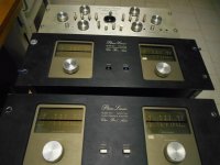
I am rebuilding a pair of Phase Linear 700 series II's with new White Oak Audio control and back-plane pcb's. With most of the mods completed on the first amp, I am measuring a voltage 'coupling' or leakage between the primary and secondary.
With a Fluke DVM between the primary coil (neutral side) and the secondary winding centre-tap; there is 62 VAC, dropping to 43 V when the meter is shunted by a 1 Meg resistor...and down to 0.64 V with 10k shunt.
Just wondering if anyone has issues with primary to secondary leakage in power transformers, acceptable limits, etc,
Thanks and Happy New Year, Peter in Canada
PS; the PL transformer apparently is the most reliable part of these amplifiers and I have found no documented issues
Attachments


Here; all was going well with new PCB's and outputs installed. Amp was powered up OK with Dim Bulb Tester but when my signal generator ground was connected to the input ground, a severe hum was introduced.
Do you have the amp on a line isolation transformer?
This sounds like a bad ground loop which could damage a fair bit of stuff.
How not to blow up your test equipment
Last edited:
Hi Doug;
I am not using an isolation transformer. Don't all transformers isolate, unless they are auto transformers? 42 VAC across 1 Meg is a leakage current of 42 uA. Could this be acceptable?
Hi Turk;
I've triple checked the input wiring. The original PL had all grounds tied together at the input jacks and speaker negative posts. The new White Oak mods have the input ground separated from the main ground by about 10 ohms. So this leakage would across that 10 ohms (adding to the input signal). The Leader signal generator has a 3 prong plug (closing the ground loop).
Honestly, I couldn't be sure if the Volume control had an effect on the hum level, pretty sure not. It was such an incredible level, I could smell the voice coil of my 'sacrificial' speaker. In an attempt to trace the cause of the leakage, the transformer was separated from the chassis. With the transformer mechanically and electrically separated, there was still 62 VAC from the primary to secondary centre tap (still dropping to 43 V when shunted by 1 Meg)
I suspect that the amp would behave if the chassis was securely grounded. Note the sanded rack tabs, maybe this has been a problem before(?)
The amp seemed perfect before an input was connected. Zero DC offset on both channels, bias adjusted and stable.
Attachments


Ya know, there is such a thing as inter-winding capacitance. To measure short the primary together, short the secondary together and measure the capacitance from primary to secondary.
i remember the old days when Phase Linear 700's (silver faces) where pressed into pa system service, as no other production amps at that time had their output power capability, problem always was keeping them isolated from each other (metal rack rails where a big no!no!)
all inputs where fed from isolation/repeat coils.
i still remember lugging wooden racks with two 700's and a 400 to power an old Butterfly PA
if somebody tried sanding the rack ears to reduce ground noise via a better common connection they where barking up the wrong tree imho...
another thought from a vague memory isn't there switches for a cap bypass on the input?
Last edited:
Hi Doug;
I am not using an isolation transformer. Don't all transformers isolate, unless they are auto transformers? 42 VAC across 1 Meg is a leakage current of 42 uA. Could this be acceptable?
When you connect another piece of equipment to an input and get such a violent reaction, you can be pretty sure that's a ground conflict.
There are several possibilities... your dim bulb unit could be floating the chassis of the amp 40 or so volts above ground, then when you connected a piece of grounded equipment a ton of current would flow... producing the monster hum.
Another possibility is that the socket for your dim bulb is reverse wired, causing a difference in potential between the amp and the rest of you equipment... same result, dangerous races of current.
Yes transformers isolate... but in most 3 wire cords the ground lead is strapped to the chassis... and so is the 0 volt rail from the secondary. No more isolation. Ordinarily not a problem, so long as neither of the above are true.
A dim bulb tester will allow you to power up a piece of gear under test at minimal power... but it is NOT a line isolation device. For that you need what is called a Variac... a variable transformer that isolates the device from ground.
Follow the link in my first post (it's in red) and watch Dave Jones explanation of how this kind of thing can and does blow up amps, test equipment and sometimes people. He's not kidding, this stuff really does happen.
THIS line isolating variac tranformer is what you need to do the job properly. (Click on the word "this")
Last edited:
Hi Jack:
I have been googling this and found nothing helpful yet. But so glad to hear this from you. I can certainly understand the inter-winding capacitance. It's a big transformer so there a lot of primary surface close to the secondary, but could 42 micro Amps through 1 Meg ohm be contributed to capacitance only? I don't have a capacitance tester or Hipot, is there a DIY test?
Turk!
My first Phase is an original 700, bought from "Triumph" and still have it. My system is 3 way active and everything in the rack is mounted with plastic shims, sleeves for rack screws, and plastic washers. The original 700 and the current 700B are dead quiet with the chassis floating. Yes, they all have a direct/ normal switch which inserts a cap in the signal hot path. I don't believe they have to do with anything ground-related.
Thanks Doug;
I have a variac (pictured in the background with Volt and AC ammeter. Thanks for pointing out that the Voltage drop across the bulb could cause a mess. I wired the 'DBT' with the bulb in the hot side of the line. It also has a bypass switch. The DBT was just 'in-circuit' as I was installing each row of output devices.
Thanks again for the link! At the moment, I wonder if anyone has info regarding primary to secondary Leakage / Capacitance / insulation testing etc. I measured a 24 V Hammond transformer and found similar, but much smaller primary to secondary voltage; 14 V Fluke meter only, 2.1 V shunted by 1 Meg, and 22 mV shunted by 10k ohm.
Attachments

120V dropped to 40V in 1Meg implies 2Megs leakage.
This is "zero" for practical purpose. Safety code isn't interested until current is 100X higher than 42uA.
1.4nFd or 1,400pFd would leak 60Hz this much. That's a BIG transformer. 1,000+pFd seems quite reasonable to me.
It is common on anything with digital in it to have 0.005u or more line to chassis. 0.05u was acceptable to ground 2-pin guitar amps (this apart from the more dangerous things done in that market). 50,000pFd!! Thirty times more than you observe.
there was a discussion at Phoenix Audio
Audible Transformer Hum or Noise | Phoenix Audio Community Forums
Audible Transformer Hum or Noise | Phoenix Audio Community Forums
well rusty memory and i'm usually wrong (according to my wife) and something i never completely understood about the PL's input is that the amp needs to see a ground on the supply line if there's no ground the input will behave like a differential input...using an iso/repeat coil insures the input is terminated.
are the 220k input resistors ok?
but x-former leakage could be your culprit.
are the 220k input resistors ok?
but x-former leakage could be your culprit.
waxing philosophically...last time i worked with Mr Emmet was at Laurentian University's Frasier auditorium in good old Sudbury Ont. for a pre Christmas solo performance back in the mid 90's
Peter S, thanks for explanation, it helps a lot! I honestly think it's not about amps, maybe it's about audio receiver, don't you think? Certain manufacturers do care about their products and their customers. For example, when I've got Onyko, I understood that it's one of the most reliable receivers, with clear sound as well. I mostly look for WiFi connection options, and ability of use of Dolby Atmos technology. When I was choosing a receiver on chooserator between two different models Onkyo TX-NR575 and Onkyo TX-NR585, I've taken the second one, cause it's possible for it to synchronize the sound of sources in different zones while a user maintains 5.2-channel of home theater circuit.
Last edited:
Thanks Paul;
Thanks for doing the math! I have checked a random transformer and found a similar but smaller leakage. If one coil is wrapped around the other, there HAS to be some kind of capacitive coupling. I am encouraged to hear that this transformer may be OK....a second PL700 II about to undergo the same upgrades had it's transformer disconnected yesterday and tested--same leakage voltage (current)!
The new White Oak design has the input ground separated from the chassis ground (looks like by about 10 ohms) It seems that potential on the chassis will find it's way to ground via the input shield, and add hum to the signal when dropped across the those 10 ohm resistors. An "IEC" line cord connector has been installed. The ground pin has been left disconnected but if it was tied to the star-point ground (transformer secondary centre-tap) would this not provide a better path to dissipate this leakage?
Hi D3imlay;
Thanks for that thread, I checked it out. That seems to be Joe's wrestling with a transformer that had some mechanical noise. My issue is only electrical. I have a thread on DIYaudio:
Pro Amp for home use.
which dealt with a similar issue. I resolved the noisy torroid issue with 20 dips, one week apart, in electrical varnish. Crazy but that 35 lb torroid is DEAD quiet, 3 years later!
Hi Turk, the 220K resistors, I believe it was explained to me, are there just to control noise if there was no input connected. They were replaced with new ones in this project. If they were open or shorted, I don't see these resistors in a position to introduce a ground loop. My Phase Linear addiction goes back a long way; someone from the band drove that old PL700 up from Toronto to Coldwater, just to sell it to me. I think it was 1978, I was 17! Apart from one melt-down in '78, it has been working hard up until 3 years ago until new power hungry 18" RCF subs required the Crest CA18.
I am at a stand-still at the moment. I would like to put the amp back together and experiment with grounding the chassis, but before that, I would like to feel a little more confident that the transformer is healthy. Douglas Self claims that the lines ground should be tied to amplifier ground at the input ground. Sounds like the original PL, Input ground tied to output ground and Centre tap bus, but obviously no mains ground. Grounding the input shell to the output ground is not going to be a consideration with the White Oak upgrade.
I am at a stand-still at the moment. I would like to put the amp back together and experiment with grounding the chassis, but before that, I would like to feel a little more confident that the transformer is healthy. Douglas Self claims that the lines ground should be tied to amplifier ground at the input ground. Sounds like the original PL, Input ground tied to output ground and Centre tap bus, but obviously no mains ground. Grounding the input shell to the output ground is not going to be a consideration with the White Oak upgrade.
it's not a ground loop thing ...and i'm no expert i can only pass on what i've learned about these things, and i recall the rca input ground behaving like a differential input, one of the shop tech's where i worked at the time tried to give me an explanation i did not fully understand with respect to the design of the input stage, something about the 10k at the base of Q1 and it's bypass cap.
Hi Turk;
I still suspect a ground loop in my case;
I think this matter is getting under control! I have just re-assembled the amp. As before, a connected speaker is dead quiet with no input connected and Fluke measures 60 VAC to the line ground. The sig gen is not floating, which resulted in the near smoking of the test speaker.
THIS TIME; a jumper clip was put between the wall outlet ground and the PL centre tap bus. Amp is almost perfect! A hum could be detected faintly with ear literally almost touching the speaker... It disappeared completely with the input disconnected.
I believe connection to my system should be easier, as star point topology has been observed. The signal generator has a 3 prong plug, so that's asking for trouble!
I would like to run this by the forum: Solution seems to be connect the IEC ground to the cap centre tap bus. This is where the hum is injected (from transformer) so why have it conducted through any other internal wiring?
As far as capacitive coupling leakage in the transformer, I found this:
Attachments

- Home
- Amplifiers
- Solid State
- Power transformer leakage in Phase Linear 700