So I had built my amp and posted some pics a couple weeks back. I probably have at least 40 hours into it running now.
I recently noticed that the power transformer started to physically vibrate. I can't hear it but I can feel it.
Note that this is a stereo amp where both sides are directly coupled via the respective B+,++,+++ lines.
I ran current checks through R7(B++) and R17(B+++), it's less than 15mA combined. I checked R18(KT88 cathode) on both sides and they're consuming around 50mA each. So we're going no more than 115mA at idle. The secondary is rated for 201mA.
I checked the heater secondary for any shorts and found none.

All the voltages check out as expected. The choke(also rated at 200mA) and OTs are always cool. I used an IR camera and nothing unexpected is running hot(both over and under).
The difference from the schematic is that the secondary is center tapped and goes to C3 through a full wave SS rectifier(two UF4007s).
The 5V secondary is snipped and heat-shrinked off since I'm using diodes.
The PT is running at about 111ºF(43ºC) according to my IR thermometer.
tldr; I can't find any obvious shorts and I think I'm running this transformer far under its power capability. It didn't do this when I first built it.
All of my resistors are 1W with the exception of the bleeder at R19 in the PSU, which is 2W. The hottest running one(of the 1Ws) is only dissipating around 1/4W from my measurements.
What am I missing?
I recently noticed that the power transformer started to physically vibrate. I can't hear it but I can feel it.
Note that this is a stereo amp where both sides are directly coupled via the respective B+,++,+++ lines.
I ran current checks through R7(B++) and R17(B+++), it's less than 15mA combined. I checked R18(KT88 cathode) on both sides and they're consuming around 50mA each. So we're going no more than 115mA at idle. The secondary is rated for 201mA.
I checked the heater secondary for any shorts and found none.
All the voltages check out as expected. The choke(also rated at 200mA) and OTs are always cool. I used an IR camera and nothing unexpected is running hot(both over and under).
The difference from the schematic is that the secondary is center tapped and goes to C3 through a full wave SS rectifier(two UF4007s).
The 5V secondary is snipped and heat-shrinked off since I'm using diodes.
The PT is running at about 111ºF(43ºC) according to my IR thermometer.
tldr; I can't find any obvious shorts and I think I'm running this transformer far under its power capability. It didn't do this when I first built it.
All of my resistors are 1W with the exception of the bleeder at R19 in the PSU, which is 2W. The hottest running one(of the 1Ws) is only dissipating around 1/4W from my measurements.
What am I missing?
Last edited:
Is your chassis steel (magnetic)?
Have the chassis mounting screws holding the power transformer come loose?
Have the power transformer's lamination screws come loose?
What is the RMS voltage of 1/2 secondary (end to center tap)?
From that, Calculate 1/2 secondary voltage x 1.414 = peak volts.
What is that peak voltage?
Is the voltage rating of C3 and C5 greater than the peak voltage?
Check the temperature of C3 and C5.
What is the power transformer's 6.3V current rating?
Is it 4 Amps or more?
Last edited:
Secondary question: Can anyone recommend some decent schematic capture software so I can redraw the actual full schematic outside of crappy LTSpice?
Is your chassis steel (magnetic)?
Have the mounting screws come loose?
It's an aluminum top with wood surround. Screws are still tight, I used good lock washers on them.
What is the RMS voltage of 1/2 secondary (end to center tap)?
From that, Calculate 1/2 secondary x 1.414 = peak volts.
What is that peak voltage?
Is the voltage rating of C3 and C5 greater than the peak voltage?
Check the temperature of C3 and C5.
I too considered this and double checked.
RMS voltage is 375Vish(530 peak). C3 is Kemet C4GAHUD5100AA3J, 600V DC rating and 330V AC rating. C5 is Nichicon LGN2X221MELC50, rated for 600V.
Here's the FLIR image. The box in the upper right is C3 and the one just below it is C5, they are operating quite cool(about room temp).

What is the power transformer's 6.3V current rating?
Is it 4 Amps or more?
This is the transformer. It says it's rated at 6A.
https://www.hammfg.com/files/parts/pdf/274BX.pdf
The KT88s should total 3.2A and the smaller tubes should total 300mA each, so theoretical 3.8A out of a 6A secondary, I think I should be well in the clear there too.
I should also note that the amp still sounds good. It is just something new that wasn't there originally. Right now I'm just still burning it in and maybe waiting for an eventual very clear failure.
I'm asking to see if there may be something stupid obvious that I'm overlooking before I get to that point. I wouldn't want to blow out a $100 transformer for nothing.
I'm asking to see if there may be something stupid obvious that I'm overlooking before I get to that point. I wouldn't want to blow out a $100 transformer for nothing.
Transformers can be noisy when they're struggling and some are just noisy. If you have a short circuit or if the amp is drawing more than usual current it can make it noisy. the thing to do is check it's not getting too hot.
Things to try, tighten mounting screws, make sure the mounting bolts are insulated, check you reservoir/smoothing caps for leakage, even if they're new.
Andy.
Things to try, tighten mounting screws, make sure the mounting bolts are insulated, check you reservoir/smoothing caps for leakage, even if they're new.
Andy.
make sure the mounting bolts are insulated
This is something different I haven't considered. Even though the aluminum is powder coated, I most definitely did not electrically insulate the screws between the transformer chassis and the aluminum top, and I'm sure the washers are cutting into it. I figured the coils themselves are electrically insulated and what the core contacts wouldn't matter so much. I see that the bells that are attached to the core have nylon washers, but the bells are likely electrically connected to the chassis ground. Is there something factored in here I might be missing?
Also, what would be considered "too hot"? I've been playing since I posted this. It's up to 117ºF. I would think that is extremely reasonable even if overpowered.
Last edited:
The Hammond is a regular and conventional big EI core transformer. Had used those types for my early tube power amps. Never got rid 100% from stray fields and vibration. This is simple physics, when those transformers are being forced to deliver currents, they vibrate and stray. Some do put them in steel boxes (mostly military), some mount those steel boxes on anti vibration feet to the chassis. The problem could be eased, but never solved.
Best to get mostly rid of this is to do a self calculated transformer with lots of margins for its max. power and let this thing being wind individually. Every conventional transformer that works at its maximum is vibrating, ringing and straying. I put this to an end by using toroidal mains transformers, individually made and designed to my needs. They are relative cheap, smaller, lighter in weight and are dead silent. With their outer shielding they have zero stray fields. Problem solved.
Best to get mostly rid of this is to do a self calculated transformer with lots of margins for its max. power and let this thing being wind individually. Every conventional transformer that works at its maximum is vibrating, ringing and straying. I put this to an end by using toroidal mains transformers, individually made and designed to my needs. They are relative cheap, smaller, lighter in weight and are dead silent. With their outer shielding they have zero stray fields. Problem solved.
Last edited:
I put this to an end by using toroidal mains transformers, individually made and designed to my needs. They are relative cheap, smaller, lighter in weight and are dead silent. With their outer shielding they have zero stray fields. Problem solved.
I thought about using toroidal for this very reason. What is driving me nuts about this is that I'm almost positive that it wasn't happening when I first built the amp. I'm left with a couple of states:
1) It has been vibrating like this the whole time and I only just noticed it. I have doubts about this state. I think I would have been concerned from the very start after it was running. However, it isn't beneath me to recognize my own biases and perhaps more careful attention over time - being more sensitive.
2) Something is failing and I can't see it. I will have to keep running it until something becomes obvious.
Considering the responses, I'm starting to believe it might be #1.
Thanks everyone so far for your inputs.
I was thinking more about whether the bolts have insulating sleeves on them, can't see Hammond leaving them off but you never know. Tfmr noise comes up a lot on builds, it can take a while to sort out.
"Also, what would be considered "too hot"?" Too hot to touch comfortably for a while, it does depend on individual tfmr's though.
Check actual, measured currents by using temporary sense resistors just to put your mind at rest.
Andy.
"Also, what would be considered "too hot"?" Too hot to touch comfortably for a while, it does depend on individual tfmr's though.
Check actual, measured currents by using temporary sense resistors just to put your mind at rest.
Andy.
The bolts that hold the end bells and laminations together are the ones that should have insulation sleeves over them.
The screws that hold the end bells to the aluminum chassis need to be grounded to the chassis.
Transformer windings have been known to short to the laminations/end bells.
Safety First!
I had a brand new output transformer that was shorted to the lams/end bells.
I found it out before I used it, returned it for a working one.
I think the reported issue's actual reason is called magnetostriction and is inherent to any transformer - more or less. Transformers that are knitted to the edge for economical reason, i.e. have too low turns per voltage, hence higher flux densitiy, are more prone to vibrate and hum than others.
Best regards!
Best regards!
Secondary question: Can anyone recommend some decent schematic capture software so I can redraw the actual full schematic outside of crappy LTSpice?
http://www.digikey.com/schemeit
agree on the "struggling" part. when traffos are run close to saturation limits, they vibrate and more loudly as the point of no return is reaches and the traffo started to smoke....
so first this i will do if that were my amp, calculate my total loading, filament power and plate idle dissipations and compare that to the traffo specs...
the class of service is also very important, class A imposes more on the traffo than a class AB...
if you have answers to these concerns, then we can proceed as there are lots and lots of things you can do to address the problem....
Core saturation is at its worst under no load. More volts per turn, more flux. The core itself vibrates due to the periodic trip around the hysteresis loop. High line voltage can make a very noisy transformer, and the line between barely perceptible vibration and felling like a lawnmower with an unbalanced blade is often quite thin. A few volts can make a difference. Everything also tends to loosen over time, due to the forces present. The windings themselves have forces on them, and therefore noises, that are proportional to and perpendicular to current. Those are worst under heavy load. Toroids that are dead silent with no load can make quite a racket when loaded heavily, since they are rarely varnish impregnated like many EI cores are.
Toroids can vibrate when the AC power isn't perfect. Personal, I've not experienced vibrations or noises with my toroids. And my amps have often changed locations. But I think its possible to let them ring, maybe with bad AC power or wrong technical parameters. As my transformers are always be designed with a big margin (maybe used only for half the power they are able to deliver on the core and wire sizes), they are dead silent. I learned that from other reputed manufacturers. Never design a transformer on the edge of its specs. Its called "brute force design".
Last edited:
Any power transformer can vibrate excessively with distortion on the AC line. Even harmonic distortion is always accompanied by DC - an unavoidable mathematical fact. Too much DC and you saturate on half the waveform. Toroids are just more susceptible to this because there are less volts per turn. If you wound one with the same volts per turn for a given core cross section, it would be no more susceptible to DC balance issues than an EI. No one ever does, because you can get away with less copper for normal operation at a given temperature rise. If you wind your own, you’re always free to make your own trade-offs.
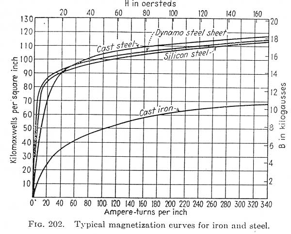
this is the magnetization curves of a traffo, flux versus magnetomotive force...
for as long as you stay below the knee of the magnetization curve, about 70maxwells/square inch, then the traffo should be fine....
i design my traffos well below the knee and that idle magnetization is quite low...
it is therefore easy to see that as more current is drawn, secondary current causes more magnetomotive force....since the turns are fixed and the magnetic path length is also fixed, therefore the current flow cause the increase and gets the traffo closer to saturation....
this is not all, inputting higher voltage in the primary than what was originally intended with the primary turns likewise causes core saturations, we have seen a lot of accidents that happened when a traffo designed for 110 was inadvertently plugged into a 220 wall outlet...
Attachments

if your traffo seems to be within the power requirements of your application, then you can dismantle the end bells, and inspect the core and the bobbin if there is space in between, then you can wedge a popsicle sick in between the coil bobbin and the core...this will quiet down your traffo...
dipping in a vat of polyurethane varnish and then drying also helps....
dipping in a vat of polyurethane varnish and then drying also helps....
Last edited:
- Home
- Amplifiers
- Tubes / Valves
- Power transformer vibrating