Hello,
I was wondering if it would be possible to power a LED from the input signal in a passive loudspeaker?
Of course the LED could be lit only after some signal would have been sent to the speaker.
Obviously some AC to DC converter should be used.
Maybe the energy from the signal could be stored in some big capacitor to smooth out the energy variations in time?
Then, how to get the correct and stable voltage?
I have used red LED in series with 10R, observing proper polarity. I won't recommend cap in parallel for obvious reasons coz direct cap on any amp output is a big NO-NO , may lead to instability.
How to make VU Meter without any ic without transistors without PCB - YouTube
I have not yet tested this circuit, It uses 2 caps
How to make VU Meter without any ic without transistors without PCB - YouTube
I have not yet tested this circuit, It uses 2 caps
Tandberg Studio Monitor | Hifisentralen
Have a look at this link. It's from Tandberg Studio Monitor. Picture a few posts down. Not exactly what you asked for but may give an idea what can be done in a crossover.
Full bridge rectifier and protection relay and bulb.
Have a look at this link. It's from Tandberg Studio Monitor. Picture a few posts down. Not exactly what you asked for but may give an idea what can be done in a crossover.
Full bridge rectifier and protection relay and bulb.
I have used red LED in series with 10R, observing proper polarity. I won't recommend cap in parallel for obvious reasons coz direct cap on any amp output is a big NO-NO , may lead to instability.
How to make VU Meter without any ic without transistors without PCB - YouTube
I have not yet tested this circuit, It uses 2 caps
So if I got it right, this design does what you are recommending not to do with the caps?
Hello,
I was wondering if it would be possible to power a LED from the input signal in a passive loudspeaker?
Of course the LED could be lit only after some signal would have been sent to the speaker.
Obviously some AC to DC converter should be used.
Maybe the energy from the signal could be stored in some big capacitor to smooth out the energy variations in time?
Then, how to get the correct and stable voltage?
You need to state your design requirements more closely.
An LED needs around 2v or more to be available to light it.
Do you want your LED to flash with the music or just to light to show audio is present at 'any' level.
You need to define the minimum loudspeaker voltage you wish to light the LED at.
A dc/dc convertor might be possible if you had at least a couple of volts DC available from rectifying the signal (minimum levels again) but it would need to be truly micropower design... a major design exercise in itself.
If you could accept having say a 9 volt battery as a power source then an LED that lights when even a few millivolts of signal is present is possible. A super high efficiency LED would run for many hundreds of hours from such a battery.
Do you want your LED to flash with the music or just to light to show audio is present at 'any' level.
You need to define the minimum loudspeaker voltage you wish to light the LED at.
I'd like to have the LED lit constantly, it's more an affirmation of the loudspeaker presence than anything else.
I'd be happy if it could be lit with the lowest possible signal coming from the speaker and I'd really like not to use a 9V battery. A battery recharged by the circuit itself when there's enough signal could be an option but I was rather thinking about some capacitor to store the energy.
A cap sounds good in practice but is fraught with difficulty. The problems are these:
1/ You need to rectify the incoming speaker voltage. That's easy but you have an immediate problem with diode voltage drop. A germanium diode probably gets you closest but will still need about 150 millivolts before it conducts.
2/ You need to build up a suitable charge on a suitable cap. Music is peaky and spiky and so there is little energy available in the signal peaks.
To give you an idea how hard this is, 1 watt/8 ohm is 4 volts peak. If you have music peaking at that level it will be way louder than you might ever imagine. Certainly a decent listening level.
And that would be about the minimum level needed to even begin to think of charging a cap to that voltage.
A big cap would take a comparatively long time to charge on such music and you would need a big cap to attempt to power an LED. It would have to maintain the voltage in the quiet bits.
Ultimately I think you have to say it won't work unless you are dealing with continually loud music playback.
The big problem is not realising just how little voltage a speaker sees in normal listening. We used to say 'keep it to 40 milliwatts please' when testing radios and the like to avoid annoying others with the volume. 40 milliwatts is around 0.5 volt rms across a speaker or just 0.7 of a volt peak. Rectify that with a germanium diode and you get about 0.5 volts DC.
Do you see the problem 🙂
I think I have posted somewhere (on this forum) an example of efficient, speaker-powered vu-meter, but I am unable to locate it.
A single pilot light should be simpler, but the difficulty is in dealing with low levels: a volt or two into a normal speaker already makes a lot of noise, meaning the circuit needs to be sensitive, and operate for a wide dynamic range.
I have developed a number of active rectifiers, capable of starting at very low voltages.
This example already operates at voltages <0.3V rms, and provides a ~lossless, doubled voltage:
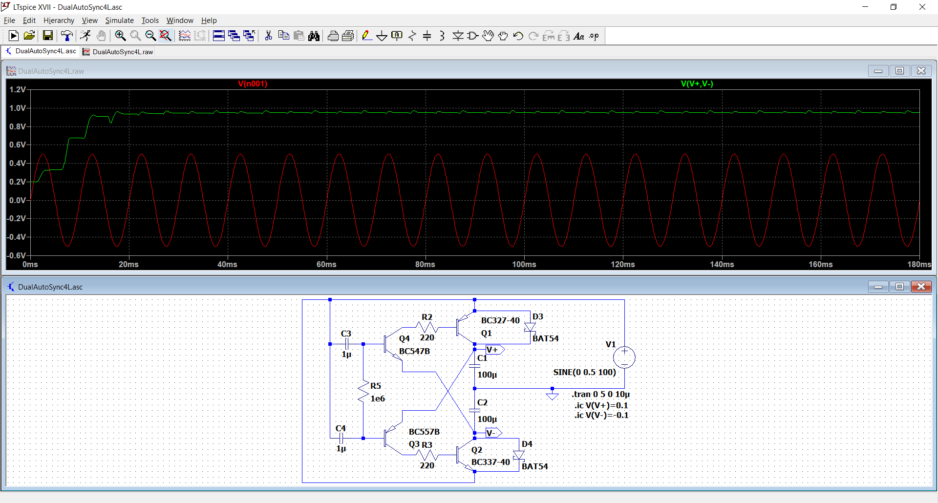
Of course, 1V is not sufficient to operate a visible LED, but one could convert the circuit into a quadrupler, or more.
A simpler option is to use a matching converter, capable of operating under 1V. I have developed such converters, using one or two transistors and a single ordinary choke.
Here is an example:
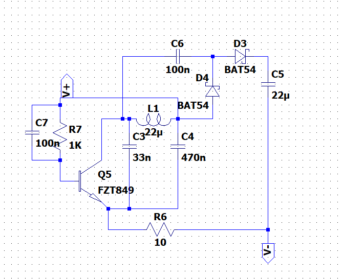
To cope with the dynamic range, one could use a FET-based CCS to control the current in the LED.
If you use a blue or blue-derived one (white, ultra-green, etc), you don't need more than 100µA or even less to get a sufficient brightness.
With germanium transistors, the circuit could start with only 150mV AC
A single pilot light should be simpler, but the difficulty is in dealing with low levels: a volt or two into a normal speaker already makes a lot of noise, meaning the circuit needs to be sensitive, and operate for a wide dynamic range.
I have developed a number of active rectifiers, capable of starting at very low voltages.
This example already operates at voltages <0.3V rms, and provides a ~lossless, doubled voltage:
Of course, 1V is not sufficient to operate a visible LED, but one could convert the circuit into a quadrupler, or more.
A simpler option is to use a matching converter, capable of operating under 1V. I have developed such converters, using one or two transistors and a single ordinary choke.
Here is an example:
To cope with the dynamic range, one could use a FET-based CCS to control the current in the LED.
If you use a blue or blue-derived one (white, ultra-green, etc), you don't need more than 100µA or even less to get a sufficient brightness.
With germanium transistors, the circuit could start with only 150mV AC
Attachments


The duty cycle of real music would be a killer here Elvee. Your circuit is super neat  but imagine it delivering 100uA to a load with a 5% duty cycle that reaches the 0.5 volts needed.
And that is still really loud on most speakers.
but imagine it delivering 100uA to a load with a 5% duty cycle that reaches the 0.5 volts needed.And that is still really loud on most speakers.
I suspect a signal transformer might be needed to boost the voltage.
What worries me is the cross-over distortion that would be introduced by adding a rectifier into the signal path. This might be negligible if this circuit wasn't in series with the speaker cable and the amp's output inductor, since the amp's feedback could cancel it out, but the non-linear currents through a rectifier or rectifiers are going to impose a voltage on this series impedance.
What worries me is the cross-over distortion that would be introduced by adding a rectifier into the signal path. This might be negligible if this circuit wasn't in series with the speaker cable and the amp's output inductor, since the amp's feedback could cancel it out, but the non-linear currents through a rectifier or rectifiers are going to impose a voltage on this series impedance.
I think something like has to be self powered (battery) to do what the op wants. A single micropower power dual opamp should configurable as a peak rectifier and hold circuit to run an LED.
In read your question as "fully passive", so powered only by signal input.
In that case, just rectify input signal (half wave o full bridge), charging a capacitor to peak voltage, and using that to drive the LED.
"Beggars don´t choose" , meaning you´ll have to accept some inconveniences:
* Leds need 1.9V DC minimum, so low Audio levels won´t turn it on.
* in principle, it will blink following Music beat.
This can be compensated for.
I wouldn´t overcomplicate it, a lot of makeup and lipstick still won´t turn a pig into a beautiful Lady.
I don't think this is a problem: a quick calculation based on your figures shows that the peak current would need to be 2mA, assuming 100% efficiency and no voltage transformation.The duty cycle of real music would be a killer here Elvee. Your circuit is super neat
Factoring in a 1:5 transformation ratio and 50% efficiency would push the peak current to 20mA, something a 8 or 16 ohm amp output could easily provide.
.And that is still really loud on most speakers
That is probably going to be the main problem.
If you design the circuit to operate at a duty cycle of 1%, with large enough smoothing caps, it could rely on the odd bass surge happening from time to time and still require ~100mA peak, which remains manageable.
The best solution would be to replace the Si transistors with Ge ones: with a 150mV sensitivity and the peak factor of normal music, the LED would remain lit for reasonably quiet listening levels
That too could be problematic, but that's the OP's choice. I do not necessarily approve it (unless it is for PA systems where ultimate sound quality is not a concern).What worries me is the cross-over distortion that would be introduced by adding a rectifier into the signal path. This might be negligible if this circuit wasn't in series with the speaker cable and the amp's output inductor, since the amp's feedback could cancel it out, but the non-linear currents through a rectifier or rectifiers are going to impose a voltage on this series impedance.
Compared to other distortion sources like thermally-induced non-linearity of the voice-coil and protection devices, the numerical value would be tiny, but the profile is much more intrusive.
I personally think that in general such a scheme should be avoided, but it can be useful in the right situations, and it is technically doable without excessive complications if required.
I was wondering if it would be possible to power a LED from the input signal in a passive loudspeaker?
it may not be very convenient, but you could induce some DC to the amp to get around/above 2V DC at the output, connect the LED with resistor and drive the loudspeaker through a (huge) NP electrolytic cap to protect the speaker from DC. the cap will influence the frequency response of the speaker!
to avoid flashing of LED or damaging it with high reverse voltage you could still use a diode and a small cap for the LED.
Hello,
I was wondering if it would be possible to power a LED from the input signal in a passive loudspeaker?....
What is the LED supposed to indicate?
//
Thanks for your contribution, but that is yet another YT video withI have used red LED in series with 10R, observing proper polarity. I won't recommend cap in parallel for obvious reasons coz direct cap on any amp output is a big NO-NO , may lead to instability.
How to make VU Meter without any ic without transistors without PCB - YouTube
I have not yet tested this circuit, It uses 2 caps
and zero data, not even a schematic. 🙄1,468,573 views - 21k likes - 520 comments
Oh well.
PS: if you build it, you do NOT need those 20V Zeners , because they are not used as such 🙄 , use plain diodes instead, 1N4148 or even plain vanilla 1N4002
PS2: 10r is too low a value and will not protect it.
Although many stand 40mA, normally I would not surpass 20mA which means minimum series resistor is peak voltage/20mA
Say for a 100W/8 ohm amplifier, peak will be 40V, so minimum safe "use everywhere" resistor is 2k, say 2k2 for a more common value.
Last edited:
Why do you need to find the speaker?
In the dark?
2 AA cells withe a limiting resistor would work for many hours.
Or, the Japanese low end cassette system, resistor to LED from speakers, but it will blink with VU.
Or use a VU meter circuit, one LED always on.
In the dark?
2 AA cells withe a limiting resistor would work for many hours.
Or, the Japanese low end cassette system, resistor to LED from speakers, but it will blink with VU.
Or use a VU meter circuit, one LED always on.
It's for a concert hall, the idea is only to enhance the visual presence of the speaker.
I understand some batteries would do the job but I think it would be a much elegant design if the energy could be taken from the audio signal.
I understand some batteries would do the job but I think it would be a much elegant design if the energy could be taken from the audio signal.
- Home
- Design & Build
- Construction Tips
- Powering a LED from the input signal in a passive loudspeaker?