Hello,
Is it fine to power two PSU from same transformer(different voltages)[book=]%[/book]. Please see image.
Transformer is 1000VA ( Transformer secondary wires are 2.5 sq mm)
0-28-36
0-28-36
Diode - GBPC3506 - four
Need to run two different PSU from same transformer(different voltages)
Is it fine to to connect 0V wire to two diodes as show in Image. This is for F5T v2(Mono) and Aleph2 (Mono) fed from same transformer.
Thank you
Attachments


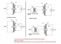
Why not link the two "0"s from the transformer, make that GND, and use half the bridges?
If you want to have separate GNDs, then your scheme may look like it will do that, but it won't, because the grounds are linked through the diodes when they conduct, so you'll get some diode Vfs between your grounds, which looks impractical...
If you want to have separate GNDs, then your scheme may look like it will do that, but it won't, because the grounds are linked through the diodes when they conduct, so you'll get some diode Vfs between your grounds, which looks impractical...
Red = +
Blue = -
Black = "GND"
Please say if I completed the schematic correctly on the 36V side.
When the diodes conduct, there will be a voltage between your two grounds, equal to the difference in Vf between two diodes having different currents...
If you link the two amps via RCAs this will make huge AC current flow in the shields, in fact a significant proportion of your rectifier current will flow in your audio cable shields, therefore, this should make epic amounts of hum.
Attachments

Last edited:
It'll even work with one bridge, no?
Jan
He wants two symmetric supplies with different voltages, so that needs two bridges.
That said, if the reason is one amp needs less volts, then fine, but if the reason is to get more power then, warning: if this is a multitap windind, the current for the 36V winding also flows in the 28V winding, so you should pay attention to the max current rating of the 28V windings, which will carry current for both amps.
Thank you
I am setting up two amplifiers(mono) in one chassi(F5T and Aleph2) so need two different voltages, thats the only reason.
Yes, this is multi tap. Since its rated 1000VA, can we assume that wire gauge should be able to handle that much current?
I am setting up two amplifiers(mono) in one chassi(F5T and Aleph2) so need two different voltages, thats the only reason.
Yes, this is multi tap. Since its rated 1000VA, can we assume that wire gauge should be able to handle that much current?
Last edited:
Assuming you only want to power ONE amplifier at a time this might be the answer.
Join the 0 volt wires together, they become your 0 volt and or ground reference.
2 bridges, 2 capacitor banks, etc.
Remember you will get 1.4 times the AC voltage at the capacitors so 36 volts AC will be 50 volts DC off load.
Join the 0 volt wires together, they become your 0 volt and or ground reference.
2 bridges, 2 capacitor banks, etc.
Remember you will get 1.4 times the AC voltage at the capacitors so 36 volts AC will be 50 volts DC off load.
Attachments

Assuming you only want to power ONE amplifier at a time this might be the answer.
This will also work with both amps on at the same time...
....
Join the 0 volt wires together, they become your 0 volt and or ground reference.
.......
something is wrong with that sentence
however, damn semantics, but Voltmeter shouldn't lie
Attachments
Good point Zen Mod,
Yes I have assumed the phasing is correct if the two 0 volt wires are joined. Otherwise the transformer will not be symmetrical when 'stacked'. And the scheme will not work...
As you say, a quick voltage check will soon confirm the situation.
Yes I have assumed the phasing is correct if the two 0 volt wires are joined. Otherwise the transformer will not be symmetrical when 'stacked'. And the scheme will not work...
As you say, a quick voltage check will soon confirm the situation.
Last edited:
you assumed correctly, but "0 Volts" somehow ringed wrong to my ears, though - maybe it's just me, today
🙂
that's why I posted little pic which can't be "just me, today"
🙂
that's why I posted little pic which can't be "just me, today"
Thank you guys
So Join the two 0V wires and measure the voltage between 28V wires(Secondary AC) and between two 36V wires(Secondary AC). It shouldn't be zero.
Instead of using 4 bridge rectifiers, I can do it with just two and still be able to run two PSU of two different voltages at same time.
So Join the two 0V wires and measure the voltage between 28V wires(Secondary AC) and between two 36V wires(Secondary AC). It shouldn't be zero.
Instead of using 4 bridge rectifiers, I can do it with just two and still be able to run two PSU of two different voltages at same time.
Yes test it by joining the 0 to the other 0. If you measure 2 x 28 and 2 x 36 volts AC all is well they are 'in phase'.captJackSparrow; said:So Join the two 0V wires and measure the voltage between 28V wires(Secondary AC) and between two 36V wires(Secondary AC). It shouldn't be zero.
If you measure a lot less than that they are out of phase and it will not work.
You only need 2 bridges (one for each voltage) and yes it will supply both at the same time, but be aware that the 28 volt secondaries carry both currents. That is the limiting factor, I do not know how much current each amplifier draws so was cautious.

Thank you
Its 0V, so as you said it will not work.
Is there any way to make it work or I need to change transformer.
Its 0V, so as you said it will not work.
Is there any way to make it work or I need to change transformer.
- Home
- Amplifiers
- Pass Labs
- Powering two PSU from one Transformer