Hello All,
I have decided to open up my recently acquired PS Audio GCPH to see what could be in need of upgrading. 😎 From what I gather, the primary parts in need of replacement are diodes, signal path resistors and electrolytic caps. Below is an example of what one modification outfit uses in place of the stock parts:
4 x Japanese Riken ½ and 1 watt signal-path carbon resistors (gold-plated leads)
4 x International Rectifier Hexfred ultra-fast soft-recovery rectifying diodes
4 x BlackGate ultra-premium FK-Series electrolytic capacitors
I plan on also replacing the output jacks and experimenting with internal wiring at some point in the future but I think the internal upgrades will be the most logical place to begin with.
My dilemma is locating the right parts and determining their values. I do have a multimeter but need to confirm that I am indeed replacing the correct parts.
Any help provided in regards to location and identification of the parts listed above would be greatly appreciated.
Having some troubles uploading pictures of the internals for illustration but will keep trying.
Link to pictures of the PS Audio GCPH internals:
ImageShack® - Online Photo and Video Hosting
ImageShack® - Online Photo and Video Hosting
ImageShack® - Online Photo and Video Hosting
ImageShack® - Online Photo and Video Hosting
Update: I contacted PS Audio tech support and requested a GCPH service diagram / schematic. They responded saying they did not have this data to share to end users.
The (4) diodes which need replacing I believe are the ones located to the lower right on the board (when viewing from above) situated in a row. The (4) electrolytic caps I believe are the small ones located in pairs to the middle left and middle right and just in front of the large caps on the center of the main board. The 1/2 and 1W signal path resistors though I am not sure of and have no idea of how to locate without a schematic or service diagram. The other parts and their locations are just speculation but I think my guesses are logical? Could be mistaken though.....😕
Any thoughts?
Any thoughts?
Yeah I suspect you are right WRT to the caps and rectifiers, but I suspect that the real action would be inside the gain cells which are probably inaccessible. I'm not sure whether or not any of the suggested changes would result in a significant improvement in performance given all of the complexity. I'd do no more than the caps and rectifiers frankly,
An inveterate tweaker am I, (see old zhaolu thread) but in this case I think you'd be better off enjoying it as is, and then selling it along when you have outgrown it sonically. I've little doubt that there are a plethora of better sounding designs here if you are in the mood for some serious DIY. (Take a look at some of Salas' stuff for ideas)
An inveterate tweaker am I, (see old zhaolu thread) but in this case I think you'd be better off enjoying it as is, and then selling it along when you have outgrown it sonically. I've little doubt that there are a plethora of better sounding designs here if you are in the mood for some serious DIY. (Take a look at some of Salas' stuff for ideas)
Last edited:
kevinkr, Thanks for your input. In addition to the diodes and caps, the generic signal path resistors that currently reside on the board are also something which I believe may be hampering the performance of this piece by quite a bit. Now, if I could only locate them......😕
Regarding the diodes, does anyone know what setting to use on the multimeter to measure their values?
This is assuming they are not already marked on the parts.
Regarding the diodes, does anyone know what setting to use on the multimeter to measure their values?
This is assuming they are not already marked on the parts.
studem, thanks.
Any idea on how to identify and locate the (4) signal path resistors?
Values should be 1/2W and 1W
Any idea on how to identify and locate the (4) signal path resistors?
Values should be 1/2W and 1W
those are going to be big ones if they are SMD
follow the traces from the input and output jacks
inside the gain cells?
follow the traces from the input and output jacks
inside the gain cells?
Chris...
What are you trying to achieve? There are a lot more than 4 resistors in the signal path. Are you just trying to duplicate the Parts Connexion mods (as sold by Underwood)?
Their use of Rikkens suggest that they replace a few resistors to color the sound a certain way-not necessarily to make the unit more resolving, and certainly not to lower noise/distortion (as carbon resistors are generally noisier than the OE metal films).
The GCPH has a pretty sophisticated circuit, and I would suspect that just changing a few resistors is not going to have much of an impact on the sonics. On the other hand, power supply mods could make a big difference in noise floor and dynamic expression. Replacing power supply diodes with something really quiet can help, but even better would probably be replacing the existing voltage regulators with discrete regs, or even shunt regs. I am almost certain that the GCPH uses pretty standard IC chip regulators-these would be the first thing I would mod...
good idea and i tend to agree.
start with the PS and go from there
what are the three pin devices with heat sinks? one for + rail and one for - rail perhaps?
start with the PS and go from there
what are the three pin devices with heat sinks? one for + rail and one for - rail perhaps?
[special= those are going to be big ones if they are SMD
follow the traces from the input and output jacks
inside the gain cells? ]%[/special]
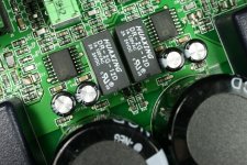
Thanks, had not considered removing the gain cells for inspection of input signal. My thoughts were the signal path resistors were the tiny ones located in pairs just under the right and left channel pairs of electrolytic caps in the picture. Of course this was merely speculative.
Close up of the diodes also attached.
follow the traces from the input and output jacks
inside the gain cells? ]%[/special]
Thanks, had not considered removing the gain cells for inspection of input signal. My thoughts were the signal path resistors were the tiny ones located in pairs just under the right and left channel pairs of electrolytic caps in the picture. Of course this was merely speculative.
Close up of the diodes also attached.
Attachments

what are the three pin devices with heat sinks? one for + rail and one for - rail perhaps?
Not sure, here is a closeup.
Attachments

What are you trying to achieve? There are a lot more than 4 resistors in the signal path. Are you just trying to duplicate the Parts Connexion mods (as sold by Underwood)?
Pretty much, as these were the only guidelines I had for the baseline on internal upgrades.
Their use of Rikkens suggest that they replace a few resistors to color the sound a certain way-not necessarily to make the unit more resolving, and certainly not to lower noise/distortion (as carbon resistors are generally noisier than the OE metal films).
Thanks for your observation and this may contribute to the more musical sound described within their ad. Maybe its just what the doctor ordered per se but can only speculate at this point.
The GCPH has a pretty sophisticated circuit, and I would suspect that just changing a few resistors is not going to have much of an impact on the sonics. On the other hand, power supply mods could make a big difference in noise floor and dynamic expression. Replacing power supply diodes with something really quiet can help, but even better would probably be replacing the existing voltage regulators with discrete regs, or even shunt regs. I am almost certain that the GCPH uses pretty standard IC chip regulators-these would be the first thing I would mod...
That sounds like a good plan but will need to first determine the exact parts/locations and their values. Contact PS Audio directly for a service schematic or circuit diagrams, neither of which they were willing to supply.
Attachments

Parts...
Google is your friend-the three pin devices with the heat sinks are very likley the main voltage regulators (there may also be secondary regulators, much smaller, as 6 pin ICs on the board). Read the part number on the the three pin devices and use the internet to find out what they are and relevant specs.
The main power supply diodes will be easy to find by locating the input traces from the transformer. The first components the power hits after the transformer will almost certainly be the diodes-these are the black tubular shaped components with the silver ring at one end. They will also be marked on the board with a designator: D followed by a number (likely D1, D2, D3, and D4). Replace these with something which features really soft recovery (read data sheets). I would replace the main power supply caps (the big ones) with something really good, a high quality compact cap that will likely fit is the Mundorf Mlytic.
The gain cells can benefit from the addition of small (1 uF-.1 uF) power supply bypass caps at the opamps-but this is a pretty advanced mod.
The regs are +/- 15 volt, Swapping them for better regs, salas shunt, tentlabs shunt, teddyregs, superreg, ALSW regs, Paul Hynes regs, Dexa regs, any of the usual suspects will bring some improvement.
The gain cells will be 'potted no point trying to look at them.
The gain cells will be 'potted no point trying to look at them.
actually...
The Gain Cells in more recent PS Audio products are not potted, they just have a cover on them-the cover can be removed and mods can be done. But modding the gain cells would definitely require advanced skills, as the boards are very compact and highly populated with SMD components.
The Gain Cells in more recent PS Audio products are not potted, they just have a cover on them-the cover can be removed and mods can be done. But modding the gain cells would definitely require advanced skills, as the boards are very compact and highly populated with SMD components.
6 months on....
I met someone at the Munich HiFi show who indeed modified a PS Audio GCPH. He apparently had much help from a few diy'ers. It was a late type around 2009. It wasn't easy but new shunt regulators were fitted with an outboard supply and some 'audio board' mods were done.
The crux of it all...the mods did nothing much and he ended up buying the small Whest Audio whestTWO which he said totally outperformed it! he even compared the whestTWO to a new GCPH and realised he wasted his money to start.
I only remember that story because I just bought my son a b-graded whestTWO from whest audio direct after listening to a friends BIG whest stage.
Sometimes it's pointless modifying a piece of kit as a better performing unit is just around the corner for less money and time!
- Status
- Not open for further replies.
- Home
- Source & Line
- Analogue Source
- PS Audio GCPH modification