Who have tested this amp could you please comment about this Q17 amp sound? Comparing to FW J2, F5, Aleph J, UDNeSS v2 some other amp?
Do I need to make any changes besides transistor pin out order to use ECW20P20, ECW20N20 or MJL1302A, MJL3281AG or IXFK220N20X3, IXTK120P20T? What changes?
I am looking for amp for my mind body and soul.
Do I need to make any changes besides transistor pin out order to use ECW20P20, ECW20N20 or MJL1302A, MJL3281AG or IXFK220N20X3, IXTK120P20T? What changes?
I am looking for amp for my mind body and soul.
Hello Viltson,
I can only speak for myself, I have now set up the 13th variant of the amplifier and am enjoying the sound to the full.
I recently heard one of the test candidates from my variant 12 on Ubiq Audio model one speakers, which is an acoustic delight. Previously, the speakers played on a Mark Levinson No. 383, which sounded a bit restrained. On the Q17, the Ubiq Audio model one played deeper, much more lively, ultra accurate - the localisation in the acoustic stage is sensational with these speakers, despite the richness of detail - the details became audible, or rather, it was noticeable what the Mark Levinson was muddling up - the amplifier was in top condition, only more is not possible there.
My friend has had many amps in the top league over the last few years, but his favourite is the Q17, which is the most fun he has listening to music.
Regards Tim
I would be very interested to know if it will go further sonically than the mosfet DPA 330/380/383test tomorrow
Since the FQA36P15 will be stocked in MOUSER and others in about a year, I wonder if the IXFK220N20X3 & IXTK120P20T replacements go further sonically than the FQA46N15 & FQA36P15 pair. So I wonder if it's worth investing in about 8x more expensive power mosfets or if I'd better wait for the FQA36P15 to be stocked.IXFK220N20X3 and IXTK120P20T are drop in replacement for FQA46N15 & FQA36P15 and stage A have enough juice to drive them both.
However, I personally fall in love with FQA46N15 & FQA36P15, these are very musical and involving. In the same time, FQA46N15 & FQA36P15, are able to drive very low impedances well below 2ohm. Your Wilson's will feel the power.
Thanks & Regards,
Tibi
Thank You!
https://eu.mouser.com/ProductDetail/IXYS/IXTH44P15T?qs=cvHLLyFtoE2pISjJk5x4ew== could be a better replacement for FQA36P15.
Please keep in mind that FQA46N15 & FQA36P15 is not a pair.
Brgds
Please keep in mind that FQA46N15 & FQA36P15 is not a pair.
Brgds
.. and an even better FQA36P15 replacement https://eu.mouser.com/ProductDetail/IXYS/IXTH48P20P?qs=cvHLLyFtoE0urKSx51uW4g==
Brgds
Brgds
Read this through twice now. Please tell me what my next project should be, Q17 or F5, I'm 50:50, assuming the making part isn't an issue, just the end result. I have a 405-2 with Snook mods so its tempting to go Q17 to hear it bettered, yet you DIYAudio people salivate over the Pass designs. Class A vs Class B and the respective implementations. Both isn't an option for space or cost
Hi Snorbans,
Let me put it this way, the F5 is an amplifier that is much more sensitive to component selection than the Q17 and therefore requires much more effort to optimise.
One of the great strengths of the Q17 is that it compensates very well for component tolerances. What I also find contemporary is its particularly low power consumption. My Q17s usually have a power consumption of 20W including the protection circuits and the radio module.
I haven't had one that gets warm yet, the waste heat is really minimal. In my last concept, I also optimised the voltage/current stabilisation of the driver stage so that it works symmetrically. This is a correction adjustment to compensate for the tolerances of the MosFET (Q13 and Q14).
Since the imaging quality of the Q17 is very much dependent on the capacitors chosen and that everything is possible from ultra precise to subtly sweet, you have a very powerful foundation with the Q17. The Q17 is also sufficient for large speakers. I have now installed a transformer with 2x35V and 500W in mine, which the Q17 can use to the full and with very high efficiency.
I got the components for it from Reichelt.de, Mouser and RSonline.
Regards Tim
Hello!
Good news!
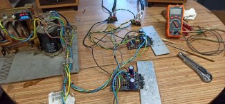
I plugged it on for few minutes and the Q17 Turbo didn't explode. I have zero DC offset. It consumes 18W idle.
I haven't done anything more so far.
Stef.
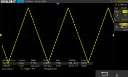
EDIT : no wobble et sinus is here.")
Good news!
I plugged it on for few minutes and the Q17 Turbo didn't explode. I have zero DC offset. It consumes 18W idle.
I haven't done anything more so far.
Stef.
EDIT : no wobble et sinus is here.
Attachments
Last edited:
Good morning,
I have a problem with the new Q17 P2 prototype.
Apparently it works fine. I have zero DC offset and if I send a sine to the input with the generator, it's good on the scope.
However, I have a problem with the voltages.
I supply the board with 50V. On ignition, the voltage is 50V on the positive and negative terminals. After a few seconds, the positive voltage drops to 46v and the negative voltage increases. If I measure the negative it starts from 50V and steadily increases 50v, 52v, 55v, 60v, 62v. There I cut so as not to destroy anything. The positive falls to him in mirror with the negative. Consumption does not move around 18W.
I really have the art of coming across problems.
I have checked everywhere but I don't see any component errors at first sight. Each component has been checked before being welded.
Does anyone have any idea where the problem is?
Stef.
I've found. It is a measurement problem. I think it comes from a potential difference that falsifies the measurements. It's probably due to the length of the power cable. If I take the GND from the power supply, everything is ok. If I measure with GND at the connector terminals on the board, it's wrong.
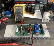
I switched the board to a 60V power supply to do the final measures et test temp.
Stef.
I switched the board to a 60V power supply to do the final measures et test temp.
Stef.
Attachments
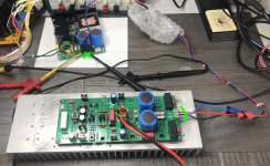
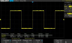
Some pictures at 53v.
R3 = 77mA
R13 = 62mA
Nothing very hot.
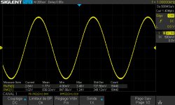
I leave it on for several hours like this to do an endurance test (with a 1vRMS output sinus).
Schematics is here : Q17-Turbo 1.0.
Stef.
R3 = 77mA
R13 = 62mA
Nothing very hot.
I leave it on for several hours like this to do an endurance test (with a 1vRMS output sinus).
Schematics is here : Q17-Turbo 1.0.
Stef.
Attachments
Last edited:
- Home
- Amplifiers
- Solid State
- Q17 - an audiophile approach to perfect sound