Not sure if this will make a difference but C16 looks to be too small a value . On the schematics i have seen it should be 4n7F yours looks more like 47pF.
Do you have or have access to instruments such as an Oscilloscope? Surely an image of this massive distortion will tell us a lot more about the fault and what likely causes it. I assume you've only built and tested 1 channel and don't have anything to compare the result with. A control device such as the duplicate channel of the stereo pair would actually be a useful asset here.
The little we could guess from your neat construction images would only be possibilities or perhaps someone does know of a problem with that PCB but there could be any number of other faults that have little to do with your board assembly work or components. My first thought though, would be a wrongly oriented diode or odd TO92 transistor pinout (not all semis nowadays comply with OEM specs).
As you can't produce significant power without distortion though, the problem is likely going to be clearly visible on the 'scope screen, using something like at least a 15W rated dummy load attached to amp. and an adjustable, clean sinewave signal applied to the input. Take care with load testing, monitoring supply current and voltage initially, though you wont need to run anything at more than a 5W or so for these tests yet.
Last edited:
Thank you for your reply. I have no test equipment other than a multi meter and know of no-one with any.(I am based in South East England)
I built 2 amps and they behave absolutely identically.
I became so disillusioned with the project I bought a genuine 606 which works perfectly.
The clone PCB follows Quad’s component layout precisely; but the clone employs a large area of earth land on the component side connected to the wiring side with two plated through holes.
Pinouts: the internet pinout info for T1 (BC214) shows emitter and collector reversed from the clone PCB. I would be willing to attempt to reverse it but worry about causing additional damage.
Check to see if some part of the pcb circuit foil is shorted to the chassis/sink on the top or bottom side.
Also ohm out the TO3 packages to see of they are properly isolated from the chassis/sink.
Of course also make sure that T1 is connected correctly. You will have to trace out the circuit
and compare it with the schematic.
Also ohm out the TO3 packages to see of they are properly isolated from the chassis/sink.
Of course also make sure that T1 is connected correctly. You will have to trace out the circuit
and compare it with the schematic.

Hmm, yours must be a lonely neighbourhood for DIYs then. Well, assuming you have a transistor test feature on the multimeter, you should be able to verify and compare with others of the type, whether yours are PNP or NPN and what the actual pinout is before you risk damage. Guides on the 'net and YouTube should yield several methods of determining pinouts with basic instruments like a DMM. otherwise, make sure when you are viewing the part that it is from the same direction as the drawing depicts it. Traditionally, US and UK drawings are projected differently and confuse as to whether you are looking at a left/right side or the top/bottom view of an object. Easiest solution would be to have a pictorial image, such as you'd take with a camera.Pinouts: the internet pinout info for T1 (BC214) shows emitter and collector reversed from the clone PCB. I would be willing to attempt to reverse it but worry about causing additional damage.
Assuming this is a kit that included the semis and components, it's been my experience that the kit makers also make mistakes with equivalent semis that have simply been re-labelled to match the original product spec. - not necessarily a bad thing if they were just competing brands of similar small-signal semis. e.g. BC547,8,9 or BC557,8,9. Even generic SC1815/SA1015 make good substitutes for those BC types - but they still have a different (JIS type) pinout, of course. I guess that the different again pinout of the original Texas Instruments type BC2XX semis probably wasn't spotted or understood by the kit maker in this case.
I have no interest in promoting products, but you should find the low cost tester linked in this ad. helpful: https://www.circuitspecialists.com/universal-component-tester-csi-tc1.html. You can buy even cheaper from other platform sellers but look closely - some offers are copies that don't have the crisp and clear OLED screen and the LCD screens I've seen on some similar type testers are truly awful - near unreadable, actually.
This is a neat, pre-built version of a well known, popular European DIY design parts tester for the needs of anyone who builds audio kits, or repairs and dabbles in audio DIY generally. It auto-senses parts and performs several appropriate tests including hFE and Vbe for matching small semis in seconds and has what you need in the way of a ZIF socket and extension leads for in or out-of-circuit and SMDs via your own custom adaptors too. The best asset is probably that it's USB rechargeable - worth more than the cost of the 9V batteries it would otherwise waste and leave you with a useless device, just when you needed it.
'Just checked a few datasheets of TI, Motorola, Onsemi and Fairchild. You guessed it; 3 different pinout arrangements - EBC, CBE and BCE for type numbers BC184-214 etc. were produced among just those manufacturers. Only Fairchild showed some indication (e.g. BC214L) that something was different about it.
I think you need to remove those semis, take out your meter and "diode test" them if you have nothing else or can't access suitable test gear etc. to identify the base at least and proceed from there, following the methods demonstrated by some YouTubers. Just type "identify transistor leads" into your browser and see what comes up. If nothing else, it can be amusing
I think you need to remove those semis, take out your meter and "diode test" them if you have nothing else or can't access suitable test gear etc. to identify the base at least and proceed from there, following the methods demonstrated by some YouTubers. Just type "identify transistor leads" into your browser and see what comes up. If nothing else, it can be amusing
Hi,Check to see if some part of the pcb circuit foil is shorted to the chassis/sink on the top or bottom side.
Also ohm out the TO3 packages to see of they are properly isolated from the chassis/sink.
Of course also make sure that T1 is connected correctly. You will have to trace out the circuit
and compare it with the schematic.
Thanks for the reply. I’m confident there are no short circuits and the TO3 isolation is good.
If T1 has been fitted collector & emitter reversed would the amp work at all, which it does on headphones?
Hi,'Just checked a few datasheets of TI, Motorola, Onsemi and Fairchild. You guessed it; 3 different pinout arrangements - EBC, CBE and BCE for type numbers BC184-214 etc. were produced among just those manufacturers. Only Fairchild showed some indication (e.g. BC214L) that something was different about it.
I think you need to remove those semis, take out your meter and "diode test" them if you have nothing else or can't access suitable test gear etc. to identify the base at least and proceed from there, following the methods demonstrated by some YouTubers. Just type "identify transistor leads" into your browser and see what comes up. If nothing else, it can be amusing
I have a transistor tester and check all transistors before fitting them.
If I were to fit T1 with emitter and collector reversed would the amp work at all, which it does on headphones usually with no audible distortion?
In total this project has cost me 1500 of my English Pounds. I am now contemplating buying an oscilloscope and signal generator;
But am dubious as to how seeing the distortion rather than hearing it will tell me how, if possible, to cure it.
That's a lot of money for a used amp, 2 DIY board kits + extras. Good though, that you do have at least a transistor tester. It removes some obstacles to fault-finding though distorted sound could be the net result of many faults, from wrongly identified parts codes or values to wrongly oriented or blown ones, connecting leads, power supply voltages and grounding. Many DIYs have been stymied by semis that weren't vetted by the kit supplier, even though they passed basic diode tests and worked after a fashion. You may already have a copy, but this service manual link is also for others who may be interested: http://www.meridian-audio.info/public/606+service+data[3127].pdf
Since the amplifier sounds fine with virtually no load but distorted with a speaker load, it also could be a problem around the current dumping bridge and output stage circuit so its worth checking voltages there, as shown on the service manual schematic to begin with, so we're certain that all components are correct and functional with diode voltage drops looking right when there is enough supply voltage to read or observe them. Sometimes, it will be easier and safer to see what's going on with only 1 pair of output transistors in circuit and an appropriately reduced reduced bias current adjustment - worth consideration when you have a little more experience to trust in your own judgement, anyway.
You made the point that what you might see on a scope still has to be interpreted correctly. We can help with that if you take a clear screen shot and post here including relevant scale/setting details but you'll probably require some further education in electronics and related workshop test procedures anyway. I have to say that Quad amps are among the rarest of linear amplifier beasts imaginable and you've bitten off an awful lot to chew with this deceptively small kit of parts. So, perhaps knuckle down and read Douglas Self's or Bob Cordell's texts on general amplifier design aspects first (free downloads of old editions can be found - e.g. https://www.desmith.net/NMdS/Data/Books and Manuals/Self - Audio Power Amp Design Handbook 4th Edn.pdf or at least follow decent quality tutorials to understand the basics and general test methods before considering the specifics of this different and still controversial Quad design.
Some good piecemeal advice can be gleaned here at DIYAudio but you really need a formal, systematic approach to learning anything of a technical nature. Some particular details of the general Quad current dumping design and this one in particular, are a bit hard to come by. 306 model is quite similar though and most details and suggestions will apply to both in cross-referencing.
Last edited:
A reversed E-C transistor "can" still work but with massively reduced gain. The 6V8 zener may protect the reversed emitter from blowing. So the lack of open loop gain could mean there is not enough feedback to lower the distortion. Into headphones the class A part of the current dumper amplifier may keeping it clean through R29, and the speaker load pushes it into current dumping through L4.Hi,
Thanks for the reply. I’m confident there are no short circuits and the TO3 isolation is good.
If T1 has been fitted collector & emitter reversed would the amp work at all, which it does on headphones?
Get some new PNPs, as the 6V reversed VEBO is a little beyond the specified maximum of 5V. Probably fine, but maybe a reduced HFE (gain)
The other thing to watch when you've fixed that is the L4 inductor. Its value matching to C8 and the resistors in the output bridge are the way the amp actually combines class A and B. That is why they should all be 1% tollerence. On the production line in Cambridgeshire the test engineer would tweak the inductor mechanically to get minimum THD on the bench, because you can't buy 1% tolerance inductors. That and saturation at higher currents into lower impedance speakers would alter the inductance and cause THD. 8ohm speakers are best with this amp.
From your brief description, it sounds rather like something's oscillating. We could look at likely causes, but really a 'scope is something worth investing in. Ebay usually has a few affordable examples - look for decent bandwidth, as high frequencies may well be involved...
Dear Ian,That's a lot of money for a used amp, 2 DIY board kits + extras. Good though, that you do have at least a transistor tester. It removes some obstacles to fault-finding though distorted sound could be the net result of many faults, from wrongly identified parts codes or values to wrongly oriented or blown ones, connecting leads, power supply voltages and grounding. Many DIYs have been stymied by semis that weren't vetted by the kit supplier, even though they passed basic diode tests and worked after a fashion. You may already have a copy, but this service manual link is also for others who may be interested: http://www.meridian-audio.info/public/606+service+data[3127].pdf
Since the amplifier sounds fine with virtually no load but distorted with a speaker load, it also could be a problem around the current dumping bridge and output stage circuit so its worth checking voltages there, as shown on the service manual schematic to begin with, so we're certain that all components are correct and functional with diode voltage drops looking right when there is enough supply voltage to read or observe them. Sometimes, it will be easier and safer to see what's going on with only 1 pair of output transistors in circuit and an appropriately reduced reduced bias current adjustment - worth consideration when you have a little more experience to trust in your own judgement, anyway.
You made the point that what you might see on a scope still has to be interpreted correctly. We can help with that if you take a clear screen shot and post here including relevant scale/setting details but you'll probably require some further education in electronics and related workshop test procedures anyway. I have to say that Quad amps are among the rarest of linear amplifier beasts imaginable and you've bitten off an awful lot to chew with this deceptively small kit of parts. So, perhaps knuckle down and read Douglas Self's or Bob Cordell's texts on general amplifier design aspects first (free downloads of old editions can be found - e.g. https://www.desmith.net/NMdS/Data/Books and Manuals/Self - Audio Power Amp Design Handbook 4th Edn.pdf or at least follow decent quality tutorials to understand the basics and general test methods before considering the specifics of this different and still controversial Quad design.
Some good piecemeal advice can be gleaned here at DIYAudio but you really need a formal, systematic approach to learning anything of a technical nature. Some particular details of the general Quad current dumping design and this one in particular, are a bit hard to come by. 306 model is quite similar though and most details and suggestions will apply to both in cross-referencing.
Thank you for your advice so far. I must point out my 606 clone was not purchased as a kit but as PCBs only (a full kit was not offered, unlike the 405 clone). Every component has been bought individually by me from established sellers on eBay. In a couple of critical instances I have been able to source inductors direct from Quad’s own spares and repair facility here in England. With the many disasters which I have accidentally engineered into the project, every transistor and many other components have had to be bought in duplicate which will often have been from a different seller from the first one I used. Also, I seriously damaged both genuine 606 amps by my own carelessness but was able to return both to correct operation by use of my increasingly large collection of spares - mostly transistors, but often resistors, diodes and capacitors.
Another contributor on a local DIY site opined, like you, that if the amp worked on headphones but not speaker then the current dumping area was faulty.
I have today made a purchase of a very old (1970) oscillator advertised as working but probably not calibrated.
I will welcome any advice you can give on how to use this.
This is the part that rings alarm bells. Ebay sellers are not normally a problem until you get down to technical issues where the sellers often have less of a clue about what they're offering than the buyer. i.e. genuine original parts, newer versions, other manufacturers, subcontracted production etc. copies, revisions and outright fakes. The problem of knowing whether the semis are close enough to spec to work in your application and like the original types, remains though.Every component has been bought individually by me from established sellers on eBay.
When you buy these probably generic semis, you get something that could work if the application is not too demanding on the specs. but there are occasions when you must have something better than "near enough".
Don't use it - not until you learn what exactly it is, whether it's a basic JLH DIY project for example, crude commercial toy etc. and you can determine its own distortion accurately. Your PC can already provide much cleaner pro quality tones, more flexible controls and multitudes of very flexible types and arrays of test tones for free. e.g. https://www.audacityteam.org/I will welcome any advice you can give on how to use this.
There seems to be an attraction for DIYS to believe only in things that reek of antiquity and 1970s technology but instruments aren't a part of the audio nor should they be hampered by the same problems as the test subject. That just leaves us stumbling about in the dark of the same old uncertainties that prevailed them.
Last edited:
I neglected to reply to your question on using an audio oscillator but that's a long story whilst the gadget is essentially only a very clean sinewave signal generator with a variable frequency range of at least 20Hz-20kHz and adjustable line level or greater output. Some have more but usually minor features like a square wave output option but its use is universal as just a stable, continuous high quality tone signal source with no further function.
All you can do with a oscillator is couple its output to the amplifier's input (say, at the aux. input), set a comfortable listening level and verify by speaker and ears that the amplifier on test does or doesn't seem to add any audible distortion over the frequency range and volume level in use. To make an accurate and more useful instrument like a distortion meter, a very low noise and distortion oscillator would be incorporated in a precision distortion meter, in order to make the necessary vanishingly small distortion measurements even possible.
If you seriously want to measure THD, there are some good and moderately good soundcard + software type audio test systems that are virtually plug and play if you know what you are trying to do and they may not cost an arm and a leg either, as an Audio Precision sys2722 analyser would. One of the better ones I've used and read of here, is the QuantAsylum QA400 series product in which the 24 bit soundcard is actually a specific type that comes with the support electronics, BNC connectors etc. in a separate, small steel case. It's currently 402 version, I think, which owes to changes in Microsoft Windows10 and the types of digital audio processor chips required that are currently available. https://github.com/QuantAsylum/QA40x/wiki/Getting-Started
https://www.diyaudio.com/community/...&c[child_nodes]=1&c[nodes][0]=121&o=relevance
Dear Mr Finch,
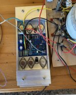
The distortion fault appears to have been my use of ferrite inductors as L2 & 3 instead of wire wound types. A commentator on a Facebook DIY group picked up on this from the photo of the amp which I posted.
2uH wire wound inductors proved very elusive when I first bought parts, but I was able to source some from Farnell here in England.
Apparently, although a ferrite inductor and a wire wound one may both show zero impedance at no load, under load the ferrite item will act as a resistor - hence the distortion.
The amp is now under test.
Yes, ferrites generally mean trouble because of their wild, non-linear response to AC (i.e. audio, RF and switch-mode power supply frequencies). The only common use in linear design audio now, would be for SMPS or perhaps RFI filtering when there is little chance of the grades of ferrite in use affecting sensitive audio circuits.
I've read several threads here and at some other forums, Websites, magazine articles etc. which emphasise the importance of the inductor properties in and around the unique Quad type output bridge network. It also pays to research your projects before taking risks with doubtful or unknown quality components for any new project, anyway. Unfortunately, if you are an Ebay type customer and buying unbranded, unqualified parts, you aren't going to know anything about their quality other than what you see in a pic and a couple of numbers stating its principal value and voltage/current rating. Maybe the pic is of a generic type that just looks like several other products and grades too.
Ferrites and audio really aren't a safe or smart combination unless you are talking of a SMPS in a shielded, well-designed and EMI verified product that was professionally designed as a system. DIY is seldom designed or built to anywhere near that standard, so don't go cheap and use whatever low cost gear that Ebay sellers offer as your quality standard. That simply wipes out any credibility of your findings. If you really want to know how good a product is or was, you need to optimise your build quality and test conditions. Assembling a circuit on a proven PCB is a good beginning but only a small and simple part of the amplifier building process. Once the likely build differences in the amplifiers are minimised, it may only demonstrate that effectively, all amplifiers will sound the same and that's probably not what you want to know.
Last edited:
- Home
- Amplifiers
- Solid State
- QUAD 606 Clone Distortion