Hello everyone!
I am currently designing a simple pass-through application for I2S audio on the STM32F072RB microcontroller. Basically it receives data on one of its I2S peripherals and forwards them to the other I2S unchanged. This is done using double buffering and a DMA is utilized on both RX and TX sides. Both I2S are in slave mode on the same clock domain. The source of the audio signal (I2S master) is the Up2Stream Mini bluetooth module from Arylic. The power end is the TAS3251 chip which takes the I2S data coming from the STM32 directly. Later I would like to enhance this application with some low/high pass filters, volume control and FFT.
But what is the problem: sometimes just after the powerup/reset the receiving I2S is somehow unable to lock on the incoming clock and that results in the entire transmission being corrupted (noise or silence coming out of the STM32 - see the video where I repeatedly reset the MCU and few occasions show the corrupted audio). I have quite isolated this problem and I am 90% sure it is caused by the receiving I2S. But what I don't know is the root cause and if it is the wrong locking on the clock, how to recover from this?
Both the receiving and transmitting DMA runs in circular mode, so there is actrually very little code to implement this whole thing - just an init and one ISR to swap the dual-buffer.
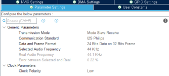
I am also attaching screenshot of the receiving I2S config.
By any chance, is there someone who has an experience with I2S audio on STM32 and can give some hints on resolving this?
Thanks and Happy New Year to everyone!
I am currently designing a simple pass-through application for I2S audio on the STM32F072RB microcontroller. Basically it receives data on one of its I2S peripherals and forwards them to the other I2S unchanged. This is done using double buffering and a DMA is utilized on both RX and TX sides. Both I2S are in slave mode on the same clock domain. The source of the audio signal (I2S master) is the Up2Stream Mini bluetooth module from Arylic. The power end is the TAS3251 chip which takes the I2S data coming from the STM32 directly. Later I would like to enhance this application with some low/high pass filters, volume control and FFT.
But what is the problem: sometimes just after the powerup/reset the receiving I2S is somehow unable to lock on the incoming clock and that results in the entire transmission being corrupted (noise or silence coming out of the STM32 - see the video where I repeatedly reset the MCU and few occasions show the corrupted audio). I have quite isolated this problem and I am 90% sure it is caused by the receiving I2S. But what I don't know is the root cause and if it is the wrong locking on the clock, how to recover from this?
Both the receiving and transmitting DMA runs in circular mode, so there is actrually very little code to implement this whole thing - just an init and one ISR to swap the dual-buffer.
I am also attaching screenshot of the receiving I2S config.
By any chance, is there someone who has an experience with I2S audio on STM32 and can give some hints on resolving this?
Thanks and Happy New Year to everyone!
Attachments
No worries. I will switch to something bigger once I get to this point. Filters are something I would like to try in the future, but I am far to that at this time.For Filters, the F0xx is too small !!!!
The project is rather big so I would prefer to go without the code. I was more like curious if anyone had issues with locking on the incoming I2S signal in the STM32 app and what could be the steps to resolve it. But one day, I will publish the code.Code ist important Here
Have you checked the I2S timings of your I2S master with an oscilloscope? STM32F072 datasheet lists the required setup and hold times.
Not the whole Code..
Init of I²S
Init of GPIOs
DMA
ISR
Especially DMA config ....
Stream Channel IS correct?
Selected Steam ISR ist correct?
Init of I²S
Init of GPIOs
DMA
ISR
Especially DMA config ....
Stream Channel IS correct?
Selected Steam ISR ist correct?
Ok, that sounds reasonable. I have put everything relevant to I2S and DMA to this excerpt. Please note that most of this code (especially the init functions) is auto generated by the STM32IDE.Not the whole Code..
C:
#define buffer_size 128

int32_t i2s_buffer_a[buffer_size];
int32_t i2s_buffer_b[buffer_size];

int32_t *i2s_rx_buffer;
int32_t *i2s_tx_buffer;

I2S_HandleTypeDef hi2s1;
I2S_HandleTypeDef hi2s2;

/**
* @brief I2S MSP Initialization
* This function configures the hardware resources used in this example
* @param hi2s: I2S handle pointer
* @retval None
*/
void HAL_I2S_MspInit(I2S_HandleTypeDef* hi2s)
{
  GPIO_InitTypeDef GPIO_InitStruct = {0};
  if(hi2s->Instance==SPI1)
  {
    /* Peripheral clock enable */
    __HAL_RCC_SPI1_CLK_ENABLE();

    __HAL_RCC_GPIOA_CLK_ENABLE();
    /**I2S1 GPIO Configuration
    PA4     ------> I2S1_WS
    PA5     ------> I2S1_CK
    PA7     ------> I2S1_SD
    */
    GPIO_InitStruct.Pin = GPIO_PIN_4|GPIO_PIN_5|GPIO_PIN_7;
    GPIO_InitStruct.Mode = GPIO_MODE_AF_PP;
    GPIO_InitStruct.Pull = GPIO_NOPULL;
    GPIO_InitStruct.Speed = GPIO_SPEED_FREQ_LOW;
    GPIO_InitStruct.Alternate = GPIO_AF0_SPI1;
    HAL_GPIO_Init(GPIOA, &GPIO_InitStruct);

    /* I2S1 DMA Init */
    /* SPI1_RX Init */
    hdma_spi1_rx.Instance = DMA1_Channel2;
    hdma_spi1_rx.Init.Direction = DMA_PERIPH_TO_MEMORY;
    hdma_spi1_rx.Init.PeriphInc = DMA_PINC_DISABLE;
    hdma_spi1_rx.Init.MemInc = DMA_MINC_ENABLE;
    hdma_spi1_rx.Init.PeriphDataAlignment = DMA_PDATAALIGN_WORD;
    hdma_spi1_rx.Init.MemDataAlignment = DMA_MDATAALIGN_WORD;
    hdma_spi1_rx.Init.Mode = DMA_CIRCULAR;
    hdma_spi1_rx.Init.Priority = DMA_PRIORITY_VERY_HIGH;
    if (HAL_DMA_Init(&hdma_spi1_rx) != HAL_OK)
    {
      Error_Handler();
    }

    __HAL_LINKDMA(hi2s,hdmarx,hdma_spi1_rx);

  }
  else if(hi2s->Instance==SPI2)
  {

    /* Peripheral clock enable */
    __HAL_RCC_SPI2_CLK_ENABLE();

    __HAL_RCC_GPIOB_CLK_ENABLE();
    /**I2S2 GPIO Configuration
    PB12     ------> I2S2_WS
    PB13     ------> I2S2_CK
    PB15     ------> I2S2_SD
    */
    GPIO_InitStruct.Pin = GPIO_PIN_12|GPIO_PIN_13|GPIO_PIN_15;
    GPIO_InitStruct.Mode = GPIO_MODE_AF_PP;
    GPIO_InitStruct.Pull = GPIO_NOPULL;
    GPIO_InitStruct.Speed = GPIO_SPEED_FREQ_LOW;
    GPIO_InitStruct.Alternate = GPIO_AF0_SPI2;
    HAL_GPIO_Init(GPIOB, &GPIO_InitStruct);

    /* I2S2 DMA Init */
    /* SPI2_TX Init */
    hdma_spi2_tx.Instance = DMA1_Channel5;
    hdma_spi2_tx.Init.Direction = DMA_MEMORY_TO_PERIPH;
    hdma_spi2_tx.Init.PeriphInc = DMA_PINC_DISABLE;
    hdma_spi2_tx.Init.MemInc = DMA_MINC_ENABLE;
    hdma_spi2_tx.Init.PeriphDataAlignment = DMA_PDATAALIGN_WORD;
    hdma_spi2_tx.Init.MemDataAlignment = DMA_MDATAALIGN_WORD;
    hdma_spi2_tx.Init.Mode = DMA_CIRCULAR;
    hdma_spi2_tx.Init.Priority = DMA_PRIORITY_VERY_HIGH;
    if (HAL_DMA_Init(&hdma_spi2_tx) != HAL_OK)
    {
      Error_Handler();
    }

    __HAL_LINKDMA(hi2s,hdmatx,hdma_spi2_tx);

  }
}


/**
  * @brief  Initializes the I2S according to the specified parameters
  *         in the I2S_InitTypeDef and create the associated handle.
  * @param  hi2s pointer to a I2S_HandleTypeDef structure that contains
  *         the configuration information for I2S module
  * @retval HAL status
  */
HAL_StatusTypeDef HAL_I2S_Init(I2S_HandleTypeDef *hi2s)
{
  uint32_t i2sdiv;
  uint32_t i2sodd;
  uint32_t packetlength;
  uint32_t tmp;
  uint32_t i2sclk;

  /* Check the I2S handle allocation */
  if (hi2s == NULL)
  {
    return HAL_ERROR;
  }

  /* Check the I2S parameters */
  assert_param(IS_I2S_ALL_INSTANCE(hi2s->Instance));
  assert_param(IS_I2S_MODE(hi2s->Init.Mode));
  assert_param(IS_I2S_STANDARD(hi2s->Init.Standard));
  assert_param(IS_I2S_DATA_FORMAT(hi2s->Init.DataFormat));
  assert_param(IS_I2S_MCLK_OUTPUT(hi2s->Init.MCLKOutput));
  assert_param(IS_I2S_AUDIO_FREQ(hi2s->Init.AudioFreq));
  assert_param(IS_I2S_CPOL(hi2s->Init.CPOL));

  if (hi2s->State == HAL_I2S_STATE_RESET)
  {
    /* Allocate lock resource and initialize it */
    hi2s->Lock = HAL_UNLOCKED;

    /* Init the low level hardware : GPIO, CLOCK, CORTEX...etc */
    HAL_I2S_MspInit(hi2s);

  }

  hi2s->State = HAL_I2S_STATE_BUSY;

  /*----------------------- SPIx I2SCFGR & I2SPR Configuration ----------------*/
  /* Clear I2SMOD, I2SE, I2SCFG, PCMSYNC, I2SSTD, CKPOL, DATLEN and CHLEN bits */
  CLEAR_BIT(hi2s->Instance->I2SCFGR, (SPI_I2SCFGR_CHLEN | SPI_I2SCFGR_DATLEN | SPI_I2SCFGR_CKPOL | \
                                      SPI_I2SCFGR_I2SSTD | SPI_I2SCFGR_PCMSYNC | SPI_I2SCFGR_I2SCFG | \
                                      SPI_I2SCFGR_I2SE | SPI_I2SCFGR_I2SMOD));
  hi2s->Instance->I2SPR = 0x0002U;

  /*----------------------- I2SPR: I2SDIV and ODD Calculation -----------------*/
  /* If the requested audio frequency is not the default, compute the prescaler */
  if (hi2s->Init.AudioFreq != I2S_AUDIOFREQ_DEFAULT)
  {
    /* Check the frame length (For the Prescaler computing) ********************/
    if (hi2s->Init.DataFormat == I2S_DATAFORMAT_16B)
    {
      /* Packet length is 16 bits */
      packetlength = 16U;
    }
    else
    {
      /* Packet length is 32 bits */
      packetlength = 32U;
    }

    /* I2S standard */
    if (hi2s->Init.Standard <= I2S_STANDARD_LSB)
    {
      /* In I2S standard packet length is multiplied by 2 */
      packetlength = packetlength * 2U;
    }

    /* Get the source clock value: based on System Clock value */
    i2sclk = HAL_RCC_GetSysClockFreq();

    /* Compute the Real divider depending on the MCLK output state, with a floating point */
    if (hi2s->Init.MCLKOutput == I2S_MCLKOUTPUT_ENABLE)
    {
      /* MCLK output is enabled */
      if (hi2s->Init.DataFormat != I2S_DATAFORMAT_16B)
      {
        tmp = (uint32_t)(((((i2sclk / (packetlength * 4U)) * 10U) / hi2s->Init.AudioFreq)) + 5U);
      }
      else
      {
        tmp = (uint32_t)(((((i2sclk / (packetlength * 8U)) * 10U) / hi2s->Init.AudioFreq)) + 5U);
      }
    }
    else
    {
      /* MCLK output is disabled */
      tmp = (uint32_t)(((((i2sclk / packetlength) * 10U) / hi2s->Init.AudioFreq)) + 5U);
    }

    /* Remove the flatting point */
    tmp = tmp / 10U;

    /* Check the parity of the divider */
    i2sodd = (uint32_t)(tmp & (uint32_t)1U);

    /* Compute the i2sdiv prescaler */
    i2sdiv = (uint32_t)((tmp - i2sodd) / 2U);

    /* Get the Mask for the Odd bit (SPI_I2SPR[8]) register */
    i2sodd = (uint32_t)(i2sodd << 8U);
  }
  else
  {
    /* Set the default values */
    i2sdiv = 2U;
    i2sodd = 0U;
  }

  /* Test if the divider is 1 or 0 or greater than 0xFF */
  if ((i2sdiv < 2U) || (i2sdiv > 0xFFU))
  {
    /* Set the error code and execute error callback*/
    SET_BIT(hi2s->ErrorCode, HAL_I2S_ERROR_PRESCALER);
    return  HAL_ERROR;
  }

  /*----------------------- SPIx I2SCFGR & I2SPR Configuration ----------------*/

  /* Write to SPIx I2SPR register the computed value */
  hi2s->Instance->I2SPR = (uint32_t)((uint32_t)i2sdiv | (uint32_t)(i2sodd | (uint32_t)hi2s->Init.MCLKOutput));

  /* Clear I2SMOD, I2SE, I2SCFG, PCMSYNC, I2SSTD, CKPOL, DATLEN and CHLEN bits */
  /* And configure the I2S with the I2S_InitStruct values                      */
  MODIFY_REG(hi2s->Instance->I2SCFGR, (SPI_I2SCFGR_CHLEN | SPI_I2SCFGR_DATLEN | \
                                       SPI_I2SCFGR_CKPOL | SPI_I2SCFGR_I2SSTD | \
                                       SPI_I2SCFGR_PCMSYNC | SPI_I2SCFGR_I2SCFG | \
                                       SPI_I2SCFGR_I2SE  | SPI_I2SCFGR_I2SMOD), \
             (SPI_I2SCFGR_I2SMOD | hi2s->Init.Mode | \
              hi2s->Init.Standard | hi2s->Init.DataFormat | \
              hi2s->Init.CPOL));

  hi2s->ErrorCode = HAL_I2S_ERROR_NONE;
  hi2s->State     = HAL_I2S_STATE_READY;

  return HAL_OK;
}


/**
  * @brief I2S1 Initialization Function
  * @param None
  * @retval None
  */
static void MX_I2S1_Init(void)
{
  hi2s1.Instance = SPI1;
  hi2s1.Init.Mode = I2S_MODE_SLAVE_RX;
  hi2s1.Init.Standard = I2S_STANDARD_PHILIPS;
  hi2s1.Init.DataFormat = I2S_DATAFORMAT_24B;
  hi2s1.Init.MCLKOutput = I2S_MCLKOUTPUT_DISABLE;
  hi2s1.Init.AudioFreq = I2S_AUDIOFREQ_44K;
  hi2s1.Init.CPOL = I2S_CPOL_LOW;
  if (HAL_I2S_Init(&hi2s1) != HAL_OK)
  {
    Error_Handler();
  }
}

/**
  * @brief I2S2 Initialization Function
  * @param None
  * @retval None
  */
static void MX_I2S2_Init(void)
{
  hi2s2.Instance = SPI2;
  hi2s2.Init.Mode = I2S_MODE_SLAVE_TX;
  hi2s2.Init.Standard = I2S_STANDARD_PHILIPS;
  hi2s2.Init.DataFormat = I2S_DATAFORMAT_24B;
  hi2s2.Init.MCLKOutput = I2S_MCLKOUTPUT_DISABLE;
  hi2s2.Init.AudioFreq = I2S_AUDIOFREQ_44K;
  hi2s2.Init.CPOL = I2S_CPOL_LOW;
  if (HAL_I2S_Init(&hi2s2) != HAL_OK)
  {
    Error_Handler();
  }
}


/**
  * Enable DMA controller clock
  */
static void MX_DMA_Init(void)
{

  /* DMA controller clock enable */
  __HAL_RCC_DMA1_CLK_ENABLE();

  /* DMA interrupt init */
  /* DMA1_Channel2_3_IRQn interrupt configuration */
  HAL_NVIC_SetPriority(DMA1_Channel2_3_IRQn, 0, 0);
  HAL_NVIC_EnableIRQ(DMA1_Channel2_3_IRQn);
  /* DMA1_Channel4_5_6_7_IRQn interrupt configuration */
  HAL_NVIC_SetPriority(DMA1_Channel4_5_6_7_IRQn, 0, 0);
  HAL_NVIC_EnableIRQ(DMA1_Channel4_5_6_7_IRQn);

}

void main(void) {

    /* Reset of all peripherals, Initializes the Flash interface and the Systick. */
    HAL_Init();

    /* Configure the system clock */
    SystemClock_Config();

    /* Initialize all configured peripherals */
    MX_DMA_Init();
    MX_I2S1_Init();
    MX_I2S2_Init();

    //start the I2S RX here. Rest will happen in the RX ISR.
    HAL_I2S_Receive_DMA(&hi2s1, (uint16_t *)i2s_rx_buffer, buffer_size);

    for(;;)
    {
    }
}

//callback function for I2S RX complete
void HAL_I2S_RxCpltCallback(I2S_HandleTypeDef *hi2s)
{
    if(hi2s == &hi2s1) {

        //once receive is complete, switch the buffers
        if(i2s_rx_buffer == i2s_buffer_a) {
            i2s_rx_buffer = i2s_buffer_b;
            i2s_tx_buffer = i2s_buffer_a;

        } else {
            i2s_rx_buffer = i2s_buffer_a;
            i2s_tx_buffer = i2s_buffer_b;
        }

        //if the other I2S is ready for TX, start it here
        if(hi2s2.State == HAL_I2S_STATE_READY) HAL_I2S_Transmit_DMA(&hi2s2, (uint16_t *)i2s_tx_buffer, buffer_size);
    }
}

/**
  * @brief  This function is executed in case of error occurrence.
  * @retval None
  */
void Error_Handler(void)
{
  __disable_irq();
  while (1)
  {
  }
}I2S that works intermittently is quite likely suffering from incompatible timings or noise in I2S signals. You can adjust the timings by changing the GPIO speed settings of I2S pins. The speed settings alter the rise and fall times which in effect changes the timings slightly. Another way to change the timings is to use series termination resistors on I2S lines (e.g. 20 to 150 ohms). But as I said before you should check with a scope that the signals and timings are according to datasheet.
Thanks for your hints. I observed the I2S signals briefly in the early stage of this project and haven't done any further checks since that. I will do some proper measurement again and will consider your ideas.I2S that works intermittently is quite likely suffering from incompatible timings or noise in I2S signals. You can adjust the timings by changing the GPIO speed settings of I2S pins. The speed settings alter the rise and fall times which in effect changes the timings slightly. Another way to change the timings is to use series termination resistors on I2S lines (e.g. 20 to 150 ohms). But as I said before you should check with a scope that the signals and timings are according to datasheet.
I missed the DMA ISR Stream functions for the selected Channel
Like
void DMA2_Stream0_IRQHandler(void) { HAL_DMA_IRQHandler(&DmaHandle);
}
And you Starting DMA Receiver...
But you must start Transmitter too ...
But if you wand to get an isr Event to Switch buffers .. you have to use
HAL_I2S_Receive_DMA_IT
And init of the pointer to buffers must be done before start of DMA ...
I would prefer Double Buffer ..
But that is a second step.
That is not correct. HAL_I2S_Receive_DMA uses interrupts and invokes process half-complete and complete callback handlers (HAL_I2S_RxHalfCpltCallback & HAL_I2S_RxCpltCallback).But if you wand to get an isr Event to Switch buffers .. you have to use
HAL_I2S_Receive_DMA_IT
Then it was changed .. again ..
But are you using the correct Stream ISR?
If you enable both ISR ....
You have to complete all ISR functions.
In principle you can enable only receive ISR ...
And use only receive complete Event to Switch buffers.
But at 44100khz .. and 128 Samples in Buffer...
Looks Like ~1400 Interrupts per second.
For a CM0 i hope it is strongly optimized
But the pointers are Zero at Startup and must be set to correct Startadress of buffers .
And both must be enabled... Receive and transmit.
Second : are the buffers in correct memory areas? DMA does not have Access to all areas.
The HAL_I2S_RxCpltCallback implementation seems a bit dodgy as it changes the receive DMA buffer pointer while DMA is running. A better solution would be to use a double sized buffer for receiving (i.e. 256) and not change the receive buffer pointer at all after receive DMA has been started. New DMA transmit would be started with appropriate buffer pointer in both HAL_I2S_RxHalfCpltCallback and HAL_I2S_RxCpltCallback. Transmit DMA would be one-off and not use circular buffers.

It IS working with circular..
But he has to Change something.
Later, Double Buffer ist a must have
DMA is running through the whole Buffer length.
ISR catches half and full
One half is for receiving .. one for Processing
The ISR is only a Mark that the First half is Sampled and can be used for audio Processing
The ISR switches only the Processing Pointer Not DMA buffers
Same for Transmitter...
One Buffer that is transmitted , one that is processed ...
With the next ISR the DMA using processed Buffer and Mark the transmitted as " can be Changed"
As said in post#4, you should first try to set your GPIO at the right speed, currently they are set up for low speed, use : "GPIO_InitStruct.Speed = GPIO_SPEED_FREQ_HIGH" for PA4, PA5, PA7 and PB12, PB13, PB15.
I usually use the method described in post#12: no circular buffer, but a linear one, twice the size used in a 'ping-pong' way using CpltCallback and HalfCpltCallback That works fine, with HAL_I2S_Transmit_DMA... and HAL_I2S_Receive_DMA functions called from within the two callback ISR.
If you want to apply some filtering and volume control you should make this into the TAS3251 it runs 32 bits biquads and has been designed for this task.
Never used F0, but in some F4, there was errata for I2S in slave mode:the receiving I2S is somehow unable to lock on the incoming clock
In I2S Slave mode, WS level must be set by the external master
when enabling the I2S
Description
n Slave mode, the WS signal level is used only to start the communication. If the I2S (in
Slave mode) is enabled while the master is already sending the clock and the WS signal
level is low (for I2S protocol) or is high (for the LSB or MSB-justified mode), the slave starts
communicating data immediately. In this case, the master and slave will be desynchronized
throughout the whole communication.
Workaround
The I2S peripheral must be enabled when the external master sets the WS line at:
• High level when the I2S protocol is selected.
• Low level when the LSB or MSB-justified mode is selected.
Maybe this helps?
My very old code for F407 (with SPL):
Code:
      I2S2_DMA_Init();                                    // Init I2S2 DMA
      SPI_I2S_DMACmd( SPI2, SPI_I2S_DMAReq_Rx, ENABLE);    // Enable DMA
      DMA_Cmd( Rx_DMAStream, ENABLE );

      if(0==WaitForWCLK(d)) return 0;    // Enable the I2S peripheral with the structure above if WCLK is OK
      //---
      I2S_Cmd(SPI2, ENABLE);            // Enable I2S2
[/code

where WaitForWCLK(d):

[code]
static __INLINE u8 WaitForWCLK(u8 edge){
  if(edge){
     if(0==WaitForLevel(0)) return 0;
     if(0==WaitForLevel(1)) return 0;
     return 1;
  }else{
     if(0==WaitForLevel(1)) return 0;
     if(0==WaitForLevel(0)) return 0;
     return 1;
  }
}
d=1 for Philips, and=0 for LJ and RJ.
I just checked that the same issue is also described in the errata of the F072 which I am using. Based on the description of this issue, this looks exactly as the problem that I am having! I will try to implement the workaround as a next step. Thank you very much for pointing this out!Never used F0, but in some F4, there was errata for I2S in slave mode
@saddevil @bohrok2610 @AIM65 - Guys, I really appreciate all your tips and hints! I will first try the solution proposed by altor and if that does not help, I will also consider your proposals.
Gordon001, you are welcome.
But I forget to show one function:
TOTmr1ms if counter, decremented in SysTick
WCLK_TIMEOUT - desired timeout in ms.
GPIOB->IDR & GPIO_Pin_12 - my WCLK (LRCK) is PB.12
P.S. More powerful controllers has not only I2S but also SAI, without this bug in slave mode.
Alex.
But I forget to show one function:
Code:
// looking for the nesessary clock level
// parameter:  0 - wait for 0-level
//             1 - wait for 1-level
//
// return 1 if OK, 0 if timeout occures

static u8 __INLINE WaitForLevel(u8 level){
   TOTmr1ms = WCLK_TIMEOUT;
   if(level!=0){ // wait for WCLK=1
          while (0==(GPIOB->IDR & GPIO_Pin_12)){
               if(0==TOTmr1ms) return 0;
          }
        return 1;
   }else{     // wait for WCLK=0
          while (0!=(GPIOB->IDR & GPIO_Pin_12)){
               if(0==TOTmr1ms) return 0;
          }
        return 1;
   }
}
TOTmr1ms if counter, decremented in SysTick
WCLK_TIMEOUT - desired timeout in ms.
GPIOB->IDR & GPIO_Pin_12 - my WCLK (LRCK) is PB.12
P.S. More powerful controllers has not only I2S but also SAI, without this bug in slave mode.
Alex.
@altor
I am trying your solution. I will make my own implementation as I am using the HAL library. As the first step, I have implemented only very simplified version where I basically wait for a certain state of the LRCK signal until I start the I2S reception.
This is a very crude solution but I already observed significant improvement with this. The issue still occurs but very rarely and I think this could be further fixed by implementing properly the waiting for edge on LRCK signal.
Again, thank you very much!
I am trying your solution. I will make my own implementation as I am using the HAL library. As the first step, I have implemented only very simplified version where I basically wait for a certain state of the LRCK signal until I start the I2S reception.
C:
    while (HAL_GPIO_ReadPin(LRCK_GPIO_Port, LRCK_Pin) != GPIO_PIN_RESET);    //use GPIO_PIN_SET for the other I2S mode
    status_rx = HAL_I2S_Receive_DMA(&hi2s1, (uint16_t *)i2s_rx_buffer, buffer_size);
This is a very crude solution but I already observed significant improvement with this. The issue still occurs but very rarely and I think this could be further fixed by implementing properly the waiting for edge on LRCK signal.
Again, thank you very much!
Hi Gordon,
try adding one line, and perhaps the problem will disappear:
In my example above the same thing, only with protection timeouts (in case there is no LRCK signal).
Alex.
try adding one line, and perhaps the problem will disappear:
Code:
  while (HAL_GPIO_ReadPin(LRCK_GPIO_Port, LRCK_Pin) != GPIO_PIN_SET);    //use GPIO_PIN_RESET for the other I2S mode   <<<<<<<< THIS
  while (HAL_GPIO_ReadPin(LRCK_GPIO_Port, LRCK_Pin) != GPIO_PIN_RESET);    //use GPIO_PIN_SET for the other I2S mode
    status_rx = HAL_I2S_Receive_DMA(&hi2s1, (uint16_t *)i2s_rx_buffer, buffer_size);
In my example above the same thing, only with protection timeouts (in case there is no LRCK signal).
Alex.
Last edited:
P.S.
If you look inside the HAL library, you will see that
HAL_GPIO_ReadPin(LRCK_GPIO_Port, LRCK_Pin) != GPIO_PIN_SET is exactly the same as:
LRCK_GPIO_Port->IDR & LRCK_Pin) != 1
And I'm guessing why with your code "The problem still occurs, but very rarely" - you wait for LRCK = 1 and then run HAL_I2S_Receive_DMA.
This function takes a long time, and if you get to the very end of LRCK=1, then by the time the I2S port actually initiates, it may already be LRCK=0, and there will be a problem.
That's why I look for LRCK=0 first, then LRCK=1, so I have a whole half LRCK period to initiate the I2S port!
In addition, I initialize the port in advance, and after searching for the desired edge, I enable port operation.
It’s a little more difficult to do this with HAL (but you can use LL-functions).
Alex.
Last edited:
- Home
- Source & Line
- Digital Line Level
- Receiving I2S audio on STM32 using DMA