Hi, jpc2001 here. You may remember me from such threads as Stabilizing the TA7136P-based preamp in an Onkyo A-5.
This A-5 integrated is a gift that keeps on giving. Not only can you turn its preamp into a world beater with a few cheap parts, you can do the same for the power amp.
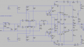
Here's the schematic and stability plots for this mod. It features:
It's surprising to get this level of performance without the use of a current mirror load for the IPS, and without a buffered or cascoded VAS.
I'll review the changes in more detail in the comments.
This A-5 integrated is a gift that keeps on giving. Not only can you turn its preamp into a world beater with a few cheap parts, you can do the same for the power amp.
Here's the schematic and stability plots for this mod. It features:
- Hugely improved stability. The factory design has quite bad phase margins, like 25 degrees.
- Hugely reduced distortion. The factory design is good for a -65 or -70dB distortion floor, with the worst case coming at larger amplitude outputs. The revised design is better than 100dB at all levels, when driving 4 ohms.
- Not that much cutting and drilling is needed. The biggest change here is the EF2 output becomes an EF3. The factory left unpopulated pads for caps across the drivers' base and collectors. We can use these for 2 out of the 3 terminals of a predriver.
It's surprising to get this level of performance without the use of a current mirror load for the IPS, and without a buffered or cascoded VAS.
I'll review the changes in more detail in the comments.
Attachments

Last edited:

Here are the differences from the factory schematic.
But I went a little further:
- Add Q5, Q6, and R11, making the output stage a triple. Most of the pads you need are there already and there's plenty of space on this huge, sparse PCB to add the rest.
- Remove the thermistor from the bias spreader, and replace the 100-ohm R631 with two series diodes. This converts it from a 4-junction drop to a 6-junction drop.
- Replace Miller caps at C609 and C611 with the TPC network shown.
- Replace the lead cap with 12pF.
But I went a little further:
- Added R14, R15, C4, and C5 to filter the input stage supply rails. This might not be necessary -- simulation suggested that PSRR wasn't too bad -- but it's cheap insurance.
- Replace R611 and R613 with 1.5mA current regulator diodes (the "current sources" in the schematic) and replaced R615 and R617 with 1.4kOhm to keep current VAS current with this change. (It would also work to use a 2.2mA or so CRD, and keep the stock values for R615 and R617.)
- Wind a small inductor (L4 in the schematic) and insert this in place of the jumper where siggnd comes into the board, to keep RF out. This unit had some history of FM radio pickup in the preamp. That RF came in through the pre-out/main-in ground lines which connects to the internal ground through this jumper, so it seemed like a good opportunity to reject some EMI there. I also relocated C603, as its factory placement would have carried RF from outside the new inductor right into the IPS.
- Deleted the factory's 3.3uF rail filter caps, and their 10nF bypass caps, from the amp PCB. Instead, add a 1uF MLCC in series with a 4.7 ohm resistor at each rail.
This project got out of hand with scope creep. The original goal was just to repair this thing and bring it up to par.
But here's the stability sim for the factory circuit. The phase margins are terribly thin. (This assumes 150nH parasitic inductors in the leads from the outputs' emitters back to the PCB, but it's only a few degrees better without those parasitics.) We can't repair it without reengineering it.
At first I thought raising the lead cap to ~15p might be enough to fix this. This at first seems to help, if you run the AC sim with the DC solve yielding a point where the output stage is idle, carrying just bias current, it gets to 45 degree phase margin. But if we use a current source to bias the OPS into class A -- simulating an operating point at "mid swing" -- the benefits of the larger lead cap vanish and it behaves no better than with the factory's 5p lead cap, both near 25 degrees of phase margin. Yuck!
Attachments

It would be nice if you wrote a detailed walk thru list of the procedures and photos of before and after the mods. I’m not tech savvy
A-5 integrated is a gift that keeps on giving
We had a few of those pass thru the shop. We moved auite a few more A-9, a lovely amplifier.
dave