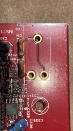
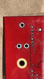
Hi fellow tinkerers. Need to source and replace a broken 1/4” horizontal surface mount instrument TS input jack for a Focusrite brand audio interface. The model is the Clarett 8PreX. It’s a HighZ input jack used for direct connection to an electric guitar, primarily.
Any help finding a solid replacement would be greatly appreciated. Because this is used for audio recording and mixing, a high quality replacement in terms of specs and build are the goal. Thanks in advance!
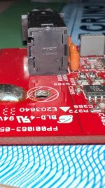
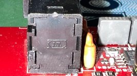
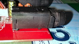
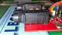
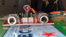
P.S. - I asked ChatGPT to analyze the photo and tell me who made the existing jack, and below was the response. I didn’t find a jack with this name in my search:
Any help finding a solid replacement would be greatly appreciated. Because this is used for audio recording and mixing, a high quality replacement in terms of specs and build are the goal. Thanks in advance!


P.S. - I asked ChatGPT to analyze the photo and tell me who made the existing jack, and below was the response. I didn’t find a jack with this name in my search:
“From the embossed “J.T.” marking and the style of the jack, it appears these are made by Changzhou Jutai Electronics Co., Ltd. (“Jutai” for short), a Chinese/Taiwanese manufacturer whose phone‐jack housings are often branded with “J.T.” in that same rectangular logo. Although Focusrite does not publicly publish the exact Jutai model number, these typically fall into Jutai’s “PJ-63x” or “PJ-62x” family of 6.35 mm (1/4″) horizontal PCB‐mount jacks.”
DigiKey, Mouser or Newark have many.
That part looks like a thru-hole rather than a surface mount.
You should remove it first and measure all the pin spacing to compare with manufacturers data sheets for an exact fit.
It may also have an internal switch.
As for brands, check Switchcraft for a quality part.
That part looks like a thru-hole rather than a surface mount.
You should remove it first and measure all the pin spacing to compare with manufacturers data sheets for an exact fit.
It may also have an internal switch.
As for brands, check Switchcraft for a quality part.
Thanks @techtool
Yes, will measure pin placement. Hoping for direction from someone who knows on other specs like switched or non switched, shielded or non shielded, max current and max voltage rating, and finding one that has same aesthetic as existing with a metal ring embedded in the input jack opening. Many of the jacks are plastic only on the input opening, no metal, including Switchcraft options for right angle 3 pin mount.
Hard find and especially to know you’ve got the right spec with an ocean of input jacks out there.
Once you get it out you can figure out if it has a switch or not by the number of pins and/or continuity testing it with an ohm meter to see how the pins connect / open when a plug is inserted.
If it does have a switch don't worry about voltage or current ratings as the switch is just used for small signal audio.
I think a direct replacement should be available once you know exactly what you have.
I've always been able to find them, but your right, there are many variations out there.
Good luck.
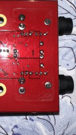
Thanks again @techtool. I should have included these pics of the underbelly of the board in my OP. When I showed these to an engineer friend, he noted this is a multilayer board where the traces are sandwiched inside the board layers. He said replacing this jack has a “rather low probability of success” which I took as engineer speak for, “impossible” in my layman’s language.
Hopefully this post helps anybody else thinking of going down this rabbit hole. Don’t do it, there’s a trap at the bottom!

Hopefully this post helps anybody else thinking of going down this rabbit hole. Don’t do it, there’s a trap at the bottom!

Well yes, it could be difficult for someone with no experience and without the right tools. Almost any PCB can be ruined in that case.
Otherwise it’s a fairly routine task for an experienced technician. Even multi-layer boards are made to be serviced.
If you are new to soldering/de-soldering and want to learn, I would suggest getting some boards from electronic junk to practice on first.
Otherwise it’s a fairly routine task for an experienced technician. Even multi-layer boards are made to be serviced.
If you are new to soldering/de-soldering and want to learn, I would suggest getting some boards from electronic junk to practice on first.
I’ve done a fair amount of soldering and desoldering, and have a desoldering pump and wick, and a weller temp selection soldering station. So if it’s doable, I’m game to try. Is there any special trick to desoldering and soldering in the multilayer PCB with internal tracing, assuming I have the correct input jack?
I like to add a little flux and/or fresh solder to the joint before removing the solder. And make sure there’s enough heat to melt it all the through to the top side. Then make sure the pins are free before you try to lift out the jack assembly. These holes are called “plated through holes” and the damage that can happen is the plating in the hole can get torn out when too much force is used when the pins are not completely free. The plating through the hole is what connects to the traces on the internal layers of the board, if any, so if it’s torn out then the board is likely not repairable.
Dude! Nice work on the de-soldering!
I'd insert a TRS jack and measure the resistance from T,R, and S to each of the three pins on the connector. I've marked the pins below to make it easier to talk about them.

I'm guessing pin 1 is connected to the sleeve (S).
Pin 2 is either connected to the ring (R) or the tip switch. If It's connected as a switch, you'll likely find that this pin connects to pin 3 when the jack is removed.
Pin 3 I'm willing to bet goes to the tip.
That's my best guess for the pinout, but measure to be sure.
Tom
I'd insert a TRS jack and measure the resistance from T,R, and S to each of the three pins on the connector. I've marked the pins below to make it easier to talk about them.
I'm guessing pin 1 is connected to the sleeve (S).
Pin 2 is either connected to the ring (R) or the tip switch. If It's connected as a switch, you'll likely find that this pin connects to pin 3 when the jack is removed.
Pin 3 I'm willing to bet goes to the tip.
That's my best guess for the pinout, but measure to be sure.
Tom
The saga continues. Full Compass, a Focusrite parts distributor, said they confirmed the correct part for this Clarett 8PreX with Focusrite. Link below. Any hot tips on soldering this bad boy to the board? I have solder with about 3% silver in it that I plan to use for the job. The part for this replacement jack is in the link:
https://www.fullcompass.com/prod/51...fire-pro-40-scarlett-8i6-scarlett-2i2-2nd-gen
https://www.fullcompass.com/prod/51...fire-pro-40-scarlett-8i6-scarlett-2i2-2nd-gen
Finished replacing/soldering in the new input jack. Feeling good about how it turned out, but open to any feedback/advice. It’s the jack on the right when looking at bottom of board/solder points, and on left when jacks are on top. I wasn’t sure what temp to use to solder to a PCB, and used 500° F to do the work.
If there is a straightforward way to test that it works without having to tear apart the interface again to reinstall the card, enlighten me please! Thanks


If there is a straightforward way to test that it works without having to tear apart the interface again to reinstall the card, enlighten me please! Thanks
The soldering looks good. I would just install and try it out.
Live testing with everything hanging out is a bit risky. If the boards touch anything metal, more damage can be done.
Simple continuity testing with a multi meter is difficult since it’s a multi layer board and hard to see where the traces from the pins go.
Live testing with everything hanging out is a bit risky. If the boards touch anything metal, more damage can be done.
Simple continuity testing with a multi meter is difficult since it’s a multi layer board and hard to see where the traces from the pins go.
- Home
- Design & Build
- Construction Tips
- Replacing Broken 1/4” Horizontal SM Jack
