Hi all,
I'm building a regulated supply for an active crossover circuit. The crossover uses 12 op2134 chips and will want +/- 15V at less than 100ma.
In the spirit of reusing, reducing, and pure cheapness I was wondering if I could employ one of the several wall wart ac/dc adaptors I have laying around. I have one of those Mac computer supplies that gives 24V, could this be used to get +/- 12V for a regulator circuit? If this is advised, how would I get the +/- 12V from the 24V and keep ground at 0.
Of course the other option is to purchase a $10 transformer and build one like Rod Elliott has on his (very informative) website.
What would the resourceful/stingy DIYers do?
If you want to use the laptop adaptor and the supply ground to connect to your split 0V then that requires a transformer.
The lazy way is just to divide the 24v in two with two identical resistors, and put a fat capacitor (1000uF or bigger) across each resistor to minimise the ground impedance. The centre point of the resistors becomes the new ground.
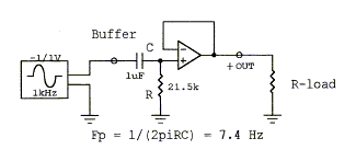
A better way is to buffer the new ground point with a power op-amp, like in the diagram. For 100mA you dont need anything as beefy as an L165, an L272 will do.
A better way is to buffer the new ground point with a power op-amp, like in the diagram. For 100mA you dont need anything as beefy as an L165, an L272 will do.
Attachments
That was going to be my suggestion, but said he wants to ground the 0V line. Gary, are you sure the power supply is already connected to mains earth?
Last edited:
This site has impressed on me the importance of safety grounding. Every piece of audio equipment I have built has a star ground to which signal ground, PS and transformer, and earth ground from my mains are connected.
This supply is not connected to safety earth but yes, I am grounding the 0V line.
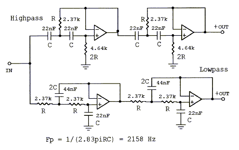
The crossover is the Siegfied Linkwitz 3 way 24 dB/oct

I also have the input buffers done

so maybe Steerpike's first suggestion would work? This is a voltage divider, right? Wouldn't the C R pair work for this with the 0V rail going to ground?
I appreciate the help, thanks,
gary
This supply is not connected to safety earth but yes, I am grounding the 0V line.
The crossover is the Siegfied Linkwitz 3 way 24 dB/oct

I also have the input buffers done

so maybe Steerpike's first suggestion would work? This is a voltage divider, right? Wouldn't the C R pair work for this with the 0V rail going to ground?
I appreciate the help, thanks,
gary
Rereading the replies above I realize my misunderstanding; creating a voltage divider would put ground at 12V, - rail at 0V and + rail at 24V. Is this correct?
Perhaps purchasing the transformer is the best idea. I'll save the Mad Max stuff for after the apocalypse.
Perhaps purchasing the transformer is the best idea. I'll save the Mad Max stuff for after the apocalypse.
Laptop power supplies, and other such "wall wart" devices, are designed to be safe without requiring grounding of the output. Use the op-amp voltage divider circuit given above. You'll end up with the 2 wires from the power supply at +12 and -12 volts, and the centre tap of the voltage divider at 0V.
In fact, connecting one side of the power supply (or, in fact, the signal ground as a whole) to the mains ground is actually less safe than keeping them separate, especially where you cannot guarantee a mains (safety) ground connection from the case to the building earth.
Consider 2 failure scenarios: One where the mains comes in contact with the case, and one where it comes in contact with the circuitry.
Also consider whether the device has a 2-wire power cord, or 3-wire cord and grounded wall socket.
Mains to case, case grounded: fuse blows. Safe.
Mains to case, no case ground: Dangerous.
Mains to circuit, signal ground to case: Same as above cases.
Mains to circuit, signal isolated from case: (relatively) safe.
Even in the last case above, the amount of "live" metal that you can come in contact with will likely be limited to fingertips on signal connectors, whereas a whole-hand grasp of a metal case would be much more dangerous.
As a general rule, if I have to connect signal and mains ground I do it at only one point, in the power amp, and make sure the amp has a 3-wire cord and grounded power outlet. All other devices in the chain either have 2-wire power cords with double-insulated class power supplies, or 3-wire cords to grounded sockets.
If your laptop PSU is not earthed then you are OK. To make things easier you might like to check out the DC splitter project on my website - it was designed for exactly your need.
- Status
- Not open for further replies.
- Home
- Amplifiers
- Power Supplies
- repurpose wall wart a good idea?
