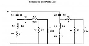
I received a manual to restore my McIntosh ML-1C's from Roger Russell before he sadly passed away earlier this year. He was the speaker designer/engineer at McIntosh Laboratories until the late 90's and designed these 4 way speakers. The tweeters are shot and the upper mids probably don't have much life left to them, so I want to do the full restoration. It calls for a supplementary crossover for the new drivers since direct replacements for these 50 year old speakers are not available. The problem I need help with is sourcing one of the coils. He specified an iron core 1.6 mH 2% 19 gauge winding (L1 in the attached schematic), but gave no other specs. I'd replace it with an air core coil but I'm afraid the DCR would be too high for the circuit and change the intended output. Any advice would be greatly appreciated.
Attachments
Any idea where I could buy a couple ferrite core 1.6 mH 2% 19 gauge inductors? Also, how much would the value of R1 change if I do not know the DCR of the original coil? Can I simply take one of higher value, say 1.8 or 2.0 mH, and remove a calculated number of windings. I do not have an LC meter to measure these.
Unless your crossover inductors were overheated by a power amp meltdown, putting DC on speaker, I wouldn't expect them to deteriorate. Shorted turns can negate any inductor, but I would expect some sign of heat, and smell. A strong DC voltage on an iron core inductor could magnetize it and make the core non-linear, but I expect a pull test of a piece of steel on the end of the bar(core) to tell one whether it is strongly magnetized or not.
Other deteriorating obvious problem in bargain speakers is electrolytic capacitors in the crossover. These have a voltage followed by "NP" on them. MacIntosh was not a bargain product. According to your schematic MacIntosh didn't use electrolytic capacitors, they used film. Film capacitor is a 100 year part unless subjected to excessive heat or current.
I'd say replace or repair your drivers, have a look around and maybe a sniff at your crossovers. I'd take a listen and look at currents through the overall speaker terminals for signs of low impedance, before I went replacing a lot of cross over parts not likely to be defective. A 1 ohm 100 W resistor series your speaker could tell you a lot about current flowing through it, with either a scope or an analog AC voltmeter. Ispeaker is voltage across 1 ohm divided by 1. Vspeaker/Ispeaker is approximately 8 or 4, whichever is correct for your speaker, you are not seeing a problem.
Last edited:
Core can allow lighter wire but reduce DCR.
19 gauge wire on a core probably around .30 to .45 DCR
There is plenty of 1.5mH core inductors using heavier 18 gauge wire.
which bring down DCR to .25
Otherwise if you use air core, it would be more bulky and expensive.
but would be heavy 14 gauge wire to have DCR around .3
Series resistor is 2 ohms. If you used the worst inductor possible
would only have to lower it to 1.5 ohms.
Not necessary since 18 gauge iron core inductors are easy to find.
And would be the same if not better than the original spec .
indianajo,
Thank you for your input. However, I incorrectly typed "replace", but I meant "substitute" as this is a new build for the modern drivers that Mr. Russell spec'd out. The original crossover still works and is used for the woofer and low mid, but the high mid and tweeter sections are disabled on that crossover and jumpered to this new one.
Thank you for your input. However, I incorrectly typed "replace", but I meant "substitute" as this is a new build for the modern drivers that Mr. Russell spec'd out. The original crossover still works and is used for the woofer and low mid, but the high mid and tweeter sections are disabled on that crossover and jumpered to this new one.
Well, you can series connect a 1.0 mH inductor 15 ga Jantzen Audio 1.0mH 15 AWG P-Core Inductor Crossover Coil
to a 0.68 mH 13 ga inductor Jantzen 5817 0.68mH 13 AWG P-Core Inductor which gets you 1.68 mH . Then you can add DC resistance to taste, both series will have less resistance than a 19 ga inductor.
Or you can buy a L meter, a 1.8 mH inductor, Jantzen Audio 1.8mH 15 AWG P-Core Inductor Crossover Coil and take some turns off until you get to 1.6 mH.
Or you can series connect two 0.8 mH 18 ga air core inductors Jantzen Audio 0.80mH 18 AWG Air Core Inductor Crossover Coil then add resistance to taste.
You know 18 g wire has less resistance than 19 ga wire don't you? Wire gets fatter as gauge number goes down.
Last month parts-express had LCR meters for $106 but today the cheapest one is $797. Stock probably sitting in a container off the port of Los Angeles. Two years ago L meter or C meter individually was $39.
Edit: typing "inductance meter" into ebay.com gets a dozen results from $17 to $95. No knowledge of these builders but you can check calibration on a known inductor from P-E.com .
Happy shopping & building.
Last edited:
I had considered most all of those alternatives before I posted on this forum. What I really wanted is exactly what is specified in Roger's document. I understand wire gauge and the properties of inductors, capacitors and resistor. He went to great lengths to keep these speakers able to reproduce 20-20K +/- 3 db (with the MQ-101 environmental equalizer to boost the low end). I am not an engineer and do not know how using values "close" to specification would affect the linearity of the speaker system. It looks like my best bet is to wind my own - I have #19 magnet wire. What I need is a source for cores and a calculator for solid core inductors.
David B. Weems Designing Building and Testing your Own Speaker System 4th ed p177 has a chart for winding coils 1.4 to 4.3 mH with 18 ga wire. 1.6 mH looks like 107 ft. Core is 1 1/2" iron.
Statement p 175 says length of wire is better inductance predictor than number of turns. I'd use one of those meters to check result before cutting off.
Statement p 175 says length of wire is better inductance predictor than number of turns. I'd use one of those meters to check result before cutting off.
Hello RealDeal,
I have 4 units and I'm gradually restoring them, new surrounds and rebuilding crossover's. I do have test equipment to measure ESR/C/L/Z. I've compared measurements of old caps to new ones ...... have found a bad 6uf cap and the ESR of new caps is anywhere between 70 and 90% less than old caps. I'd be interested in what manual you procured from Mr. Russell, I see the schematic you posted and have seen elsewhere that the drivers he specified were Morel MDT40 & MDM 55.
I have 4 units and I'm gradually restoring them, new surrounds and rebuilding crossover's. I do have test equipment to measure ESR/C/L/Z. I've compared measurements of old caps to new ones ...... have found a bad 6uf cap and the ESR of new caps is anywhere between 70 and 90% less than old caps. I'd be interested in what manual you procured from Mr. Russell, I see the schematic you posted and have seen elsewhere that the drivers he specified were Morel MDT40 & MDM 55.
I received a manual to restore my McIntosh ML-1C's from Roger Russell before he sadly passed away earlier this year. He was the speaker designer/engineer at McIntosh Laboratories until the late 90's and designed these 4 way speakers. The tweeters are shot and the upper mids probably don't have much life left to them, so I want to do the full restoration. It calls for a supplementary crossover for the new drivers since direct replacements for these 50 year old speakers are not available. The problem I need help with is sourcing one of the coils. He specified an iron core 1.6 mH 2% 19 gauge winding (L1 in the attached schematic), but gave no other specs. I'd replace it with an air core coil but I'm afraid the DCR would be too high for the circuit and change the intended output. Any advice would be greatly appreciated.
Here is the document from Roger. Also, I have procured some iron cores and building a jig to wind the coils. An EE friend has the professional meter to read the values, so after I wind them a little longer that needed, I will go to his shop and cut to the correct value. As for the caps, Roger suggested I stay with electrolytic for the original x-over, but to use polyprops for the supplemental x-over. I hope this helps you out.Hello RealDeal,
I have 4 units and I'm gradually restoring them, new surrounds and rebuilding crossover's. I do have test equipment to measure ESR/C/L/Z. I've compared measurements of old caps to new ones ...... have found a bad 6uf cap and the ESR of new caps is anywhere between 70 and 90% less than old caps. I'd be interested in what manual you procured from Mr. Russell, I see the schematic you posted and have seen elsewhere that the drivers he specified were Morel MDT40 & MDM 55.
Attachments

I'm not sure how far along you've gotten, but if you are interested I have a pair of those revised ML-1C crossovers that Roger built for me some years ago. Something I cannot now recall interrupted my project, and so the crossovers are still in the box along with some notes from Roger. I've also got an MQ-107 in the original box and with the full capacitor kit. Send me a note if any of these would help, and either way, best of luck with your project!Here is the document from Roger. Also, I have procured some iron cores and building a jig to wind the coils. An EE friend has the professional meter to read the values, so after I wind them a little longer that needed, I will go to his shop and cut to the correct value. As for the caps, Roger suggested I stay with electrolytic for the original x-over, but to use polyprops for the supplemental x-over. I hope this helps you out.
-Matt
I would be interested in the crossovers for sure.I'm not sure how far along you've gotten, but if you are interested I have a pair of those revised ML-1C crossovers that Roger built for me some years ago. Something I cannot now recall interrupted my project, and so the crossovers are still in the box along with some notes from Roger. I've also got an MQ-107 in the original box and with the full capacitor kit. Send me a note if any of these would help, and either way, best of luck with your project!
-Matt
 ]
]Hello if sbhack doesn't want them please contact me at (five-zero-4) 4 zero zero - 1737 or sbarms 62 @ g mail - thanks, SteveI'm not sure how far along you've gotten, but if you are interested I have a pair of those revised ML-1C crossovers that Roger built for me some years ago. Something I cannot now recall interrupted my project, and so the crossovers are still in the box along with some notes from Roger. I've also got an MQ-107 in the original box and with the full capacitor kit. Send me a note if any of these would help, and either way, best of luck with your project!
-Matt
- Home
- Loudspeakers
- Multi-Way
- Restoring McIntosh ML-1Cs