Hello everyone, I got my Acoustat Spectra 22's over 20 years ago, used them until we moved in 2017, and then had them stored in a fairly dry basement.
Now I tried to reconnect them and one of the speakers sounds fairly dull, compared to the other. It lacks any bass and is significantly quieter than the other speaker.
Another thing I notice is that the LEDs on the back glow very faintly, I can only see them when I switch the light off. This is the case for both speakers.
The MK-2123s seem to be the pretty late model with the 15V AC wall transformers. I am using an aftermarket 15V AC transformer.
I opened up the MK2123 this afternoon and got this:

So the 470 Ohm (?) resistor looks pretty cooked, no idea if the Zener diode is still working. Obviously there was a pretty high current running here, I wonder why. Anyone has a clue?
I will replace all electrolytic capacitors on both speakers of course.
Cheers, Robert
Now I tried to reconnect them and one of the speakers sounds fairly dull, compared to the other. It lacks any bass and is significantly quieter than the other speaker.
Another thing I notice is that the LEDs on the back glow very faintly, I can only see them when I switch the light off. This is the case for both speakers.
The MK-2123s seem to be the pretty late model with the 15V AC wall transformers. I am using an aftermarket 15V AC transformer.
I opened up the MK2123 this afternoon and got this:
So the 470 Ohm (?) resistor looks pretty cooked, no idea if the Zener diode is still working. Obviously there was a pretty high current running here, I wonder why. Anyone has a clue?
I will replace all electrolytic capacitors on both speakers of course.
Cheers, Robert
I've never seen that fault...but obviously it can happen! Did BOTH speakers suffer the same damage? If so, I would expect some external trauma - like applying too high a voltage. If both speakers exhibit similar damage, I suggest you investigate possible external causes.
But clearly some of the components need replacement. At minimum, I would replace the resistor, zener diode, and any electrolytic capacitors. Note that performance of the bias supply can be properly evaluated only with the board properly installed in the chassis, as the proximity of the metal chassis may affect its operation slightly. If the resistor adjacent to the zener is 100 ohms, change it to 470 ohms for a 15 VAC input.
While you are at it, I recommend checking that your bias supply is fully updated. If not, I recommend the update for best reliability. You will also need to check and adjust the bias voltage after any repairs. See attached documents.
Attachments
Hey there, I was kind of hoping you would see my post 😀 I did not open the second unit yet, but I have a hunch that these are very early Ultrasonic Bias Supplies, since the Speakers are from around 1989. They were sold with the 15VAC PSU to me, but maybe they were originally 12VAC powered, which might explain the overheating?
I removed the board completely today from the chassis and will apply the update. The Board differs a bit from what I see at the original Adjustment doc, for example I do not see the LED I have in it. Is there a schematic for the LED version? And another question: For the Electrolytics, any manufacturer will do?
Adjustment will be done as soon as I am finished and obtain a HV Meter. For documentation purposes, I attach two images of the Ultrasonic Bias Board, maybe you see something interesting there.


Cheers, thank you so much for your effort!
I removed the board completely today from the chassis and will apply the update. The Board differs a bit from what I see at the original Adjustment doc, for example I do not see the LED I have in it. Is there a schematic for the LED version? And another question: For the Electrolytics, any manufacturer will do?
Adjustment will be done as soon as I am finished and obtain a HV Meter. For documentation purposes, I attach two images of the Ultrasonic Bias Board, maybe you see something interesting there.
Cheers, thank you so much for your effort!
Photos show that you do need to do the update. Other than the burnt components, I don't see anything amiss. There is no board layout or schematic available for this bias supply. However, the schematic presented in the update instructions is the same circuit, minus the indicator LED. The LED is a power ON indicator only and does not confirm proper operation of the HV supply. The board layout, although not exactly the same, is very similar.
I recommend capacitors from a reputable electronics distributor. If you can find them, use 105 degree C rated electrolytic capacitors, instead of the usual 85 degree-rated parts. They tend to last longer and are only marginally more expensive. As stated in the instructions, there is no sonic advantage to using "audiophile" grade parts in this circuit.
I recommend capacitors from a reputable electronics distributor. If you can find them, use 105 degree C rated electrolytic capacitors, instead of the usual 85 degree-rated parts. They tend to last longer and are only marginally more expensive. As stated in the instructions, there is no sonic advantage to using "audiophile" grade parts in this circuit.
Hello there, I am acquiring all the necessary parts for the upgrade and refurbishing process. I encounter one quite unexpected problem:
Unfortunately, the fuse holder broke on one speaker, and I need to replace it. I bought a couple of different models on ebay and amazon, but none fit. The whole speaker connector board is designed quite exactly for this one type of fuse holder (on the left, ebay/china on the right):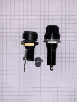
All new ones are too long, which makes it impossible to screw the connector board back in place. Does anyone know the make and model of the fuse holder? I already searched mouser electronics and did not find a good replacement.
Cheers, Robert
Unfortunately, the fuse holder broke on one speaker, and I need to replace it. I bought a couple of different models on ebay and amazon, but none fit. The whole speaker connector board is designed quite exactly for this one type of fuse holder (on the left, ebay/china on the right):

All new ones are too long, which makes it impossible to screw the connector board back in place. Does anyone know the make and model of the fuse holder? I already searched mouser electronics and did not find a good replacement.
Cheers, Robert
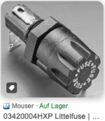
I don't have a part number, but I know the fuseholder is manufactured by Littelfuse. Here's a possibility, same part used on Hafler amplifiers.
https://www.ebay.com/itm/3726511603...dWFvyL43BcOu8DjkjMufnIa34=|tkp:Bk9SR5SAufysZA
https://www.ebay.com/itm/3726511603...dWFvyL43BcOu8DjkjMufnIa34=|tkp:Bk9SR5SAufysZA
Thank you so much, that was a valuable hint! I think I found the fuse holder on mouser, but I need to decrypt the Littelfuse data sheet 😀
Yes, I can confirm: This is perfect. So, if you ever need to replace the fuse holder, this is the choice:

On the right is the 1989 original, on the left is the 2024 replacement part. Thats 35 years, folks.
On the right is the 1989 original, on the left is the 2024 replacement part. Thats 35 years, folks.
Okay, yesterday I finished up the Bias supply update and fired it up. There was no smoke or anything (yay!), but when I used a 1000:1 40kV HV Probe at the red input to the HV cascade I read nothing. I was a bit disappointed at first, but then decided to measure the 5kV output. And voila, a bit above 4kV was there. After replacing the zener diode to a 16V one and adding a few more loops around the HV lead I was able to achieve a nice 5kV output, with the potentiometer somewhere in the middle of its range.
I have no idea why I cant measure anything on the cascade input, going along the cascade diodes with the probe I measure roughly an increase by 1kV in every step. So, thats fine, right?
I remarked that the LED is brighter now, too 😉 So I think its time to reassemble and get to the next speaker. I will add a picture of the updated bias supply later.
I suspect you had your meter set to DC volts when your tried measuring the input to the voltage multiplier. At this point, it's an AC voltage of about 750VAC. As you move along the multiplier, you will measure a DC voltage, increasing about 1000VDC per stage.
Ensure that the bias supply board is fully installed in the chassis before any final voltage adjustments, as the proximity of the metal chassis can affect the oscillator's operation. Also, most HV probes will read somewhat less than the actual voltage when measured at the red output jack, due to the supply's high output impedance, and the loading effects of the probe. If you are actually measuring 5kV with your probe, then the bias voltage may be set too high. There's no real danger in that situation, except that you may experience excessive ticks-n-pops under very humid conditions.
Ensure that the bias supply board is fully installed in the chassis before any final voltage adjustments, as the proximity of the metal chassis can affect the oscillator's operation. Also, most HV probes will read somewhat less than the actual voltage when measured at the red output jack, due to the supply's high output impedance, and the loading effects of the probe. If you are actually measuring 5kV with your probe, then the bias voltage may be set too high. There's no real danger in that situation, except that you may experience excessive ticks-n-pops under very humid conditions.
Thank you so much, I had the meter set to DC indeed, I will check again with AC. Now this explains everything 😀 I saw in your alignment instructions that the bias needs to be adjusted to 4.3kV, will do that tonight.
Cheers, Robert
Cheers, Robert
Hello Robert,
While I don't have experience with the MK-2123 series and don't know details of the input impedance of your 40kV HV Probe, it might be affecting the accuracy of the bias voltage measurement as Mr. AAM kindly replied "most HV probes will read somewhat less than the actual voltage when measured at the red output jack, due to the supply's high output impedance, and the loading effects of the probe."
A simple check of the bias voltage can be constructed using an ultra-high resistance 10,000 Megohm resistor to form a 1000:1 voltage divider with a standard 10 Megohm input DVM.
This method worked well for my Acoustat MK-121-2 interface, documented in "Acoustat Interface MK-121-2: Example of Measuring the DC High Voltage".
https://www.diyaudio.com/community/...mple-of-measuring-the-dc-high-voltage.411370/
You're welcome to try this method, hope it may be helpful.
Thank you,
John
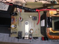
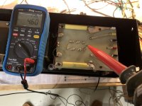
Thanks everybody, a few days ago I was able to finish the restoration of the first speaker. I was able to get a stable voltage of around 4.6 kV (after letting it stabilize for around 45 minutes). The Speaker sounds great again. I started on the second speaker yesterday and found out why the first Bias Oscillator board was so burned up: The resistor close to the zener diode was a 100 Ohm, so it was obviously meant to be used with the 12V PSUs instead of the 15V ones I got with the speakers. It wasnt that burned up like the first one, but a bit toasty. I use 470 ohm resistors in both circuits not, the components are just getting warm now.
I hope to finish the second speaker this week and look forward to listen to a lot of music.
Pics for documentation purposes:
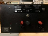
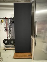
I hope to finish the second speaker this week and look forward to listen to a lot of music.
Pics for documentation purposes:


Great news! Your speakers should be ready for many more years of good listening. I'm curious about the last photo showing what appears to be a non-standard wood base. Is that something of your own creation? Normally, the base would extent only a few inches in front of the vertical array.
Hey there, I think that is more a result of my iPhones wideangle lens. I am in process of restoring the second wood base right now, and it looks like this:
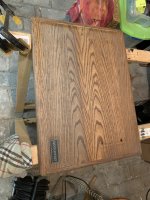
During my hunt for documentation I saw a few similar wooden bases like this. It has a stamp from a company called Custom Woodwork & Design Inc. on the bottom:
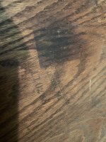
So I guess its original? I love the look of it, definitely.

During my hunt for documentation I saw a few similar wooden bases like this. It has a stamp from a company called Custom Woodwork & Design Inc. on the bottom:

So I guess its original? I love the look of it, definitely.
Those do appear to be original bases. Once Acoustat moved to Arizona, all workworking was subcontracted. The label is likely from one of those subcontractors. There were several vendors and I don't remember their names.
- Home
- Loudspeakers
- Planars & Exotics
- Restoring MK-2123 with issues
