I am putting up a calculator for speaker requirements on my web site, for speaker sensitivity, amplifier power and sound pressure level estimations.
Using information about room and speaker and speaker placement, the spl is estimated by summing the direct sound and the reverberant field.
Direct sound is easy, but I have not been able to find consistent information for the reverberant field calculation, valid in a small room with relatively much acoustic damping.
I have found different fomulas suggested, that will give different results.
So far, this is pretty much what I have now:
- Rx, the critical distance, is where the revb spl equals the direct.
- At least 2 formulas:
Rx=0.141*sqrt(G*A'), where A' is the room constant = f(V, T60, abs area), G=source directivity.
Rx=0.057*sqrt(G*V/T60), where G=source dir.
- Revb spl can then be calculated by using Rx.
- A correction factor for the revb spl can compensate approximately for the fact that the revb sound field is not constant in a small damped room, it will fall as a function of distance from the source.
[http://www.jblpro.com/pub/manuals/pssdm_1.pdf, page 58].
If someone have an idea, or even some good measurements of spl vs. distance from source in a room, that could be helpful.
If the relationship between room data (V and T60) and spl as a function of distance from the source can be established, then it will be possible to make a sufficiently accurate correction.
This does not need to be very accurate, that is also impossible with reasonable amount of data entered into the model (i.e. room dimensions and T60), but it can still be sufficient to give a good estimate.
All rooms considered as useable here will fall into the category of small and damped.
In such rooms the direct sound will be large compared to the reverberant field, in most cases larger than the revb, so that an error in estimated revb spl will not have a proportional impact on the total estimatede spl.
Hi Okv,
I use a form of what they call the "Hopkins Stryker" law for these calculations. It is probably the same equations as yours in another form. The typical equation is 2 parts with one giving the direct sound component and the second the reverberent level. I have it built into a standard acoustics spreadsheet as figuring the room constant is the starting point.
I have also done "draw away curves" to show level drop with distance. My interest in this is more to do with cinema installations. I have also measured it in the home but the contribution of the reverberant field is seldom dominant. Most listeners in most homes seem to sit more or less at the critical distance with room and direct sounds roughly in balance. This is, of course, a function of frequency and the critical distance is closer at high frequencies than at low. Rising directivity, rising absorption and even air absorption all contribute to this.
Note that the Hopkins Stryker view assumes a diffuse field and classical acoustics performance. A number of studies show that practical rooms don't have a constant reverberent field (flat draw away), but end up with some downslope for all distances. This is especially true for rooms with 1 short dimensions, such as a long and wide office areas (with a low ceiling in comparison).
If there is some interest I will drag out some measurements.
David
Linkwitz has som pretty simple and straight forward equations for the reverberant field.
Maybe that would be a place to start?
Maybe that would be a place to start?
Seems to me that you have all that you need. Toole also shows some data that you might find useful. I think that you are on the right track.
Here are a few pages from an old General Radio reference text that cover the subject succinctly.
The 2nd page gives the basic equation for both feet and meters calculations. Note that the Q over 4 pi r squared term gives the direct component and the 4 over R gives the reverberent field level. The following pages give typical plots for a variety of room R and speaker Q. Critical distance is the turnover point between the two sections of a particular curve. At the critical distance the direct and reverberent portions are equal and the sum is greater than either by 3dB (random summation).
Finally, he goes into the deviation between the ideal case and the typical measurements of a low ceiling room.
Note that this equation is important for more than speakers and their level drop with distance. It defines the relationship between PWL and SPL, that is, between a sources power level and its SPL in an environment. This is fundamental to working acousticians who are often asked to calculate the expected SPL of a noise source in an enclosure. For example, if I mount a deisel engine in a concrete shed, I need to know the radiated power of the engine and the absorption (square meters or square feet...Sabines of the shed) and based on that I can predict the internal SPL.
Basic stuff but very important.
David S.
Attachments
Basically it looks as though the "low ceiling" room (Fig. 8-10) has only a direct field. That is a curious result. Floyd found that the reverberant field dropped at 3 dB per double distance after the direct field dominance. The chart in the attached appears has more like 6 db per DD - essentially the same as a free field.
Kind of curious. Could that figure be out of date? I mean 1965! Measurements have gotten a lot better in the last 50 years!
Kind of curious. Could that figure be out of date? I mean 1965! Measurements have gotten a lot better in the last 50 years!
Measurements have gotten better, but rooms and sound propagation have not changed in the last 50 years.Basically it looks as though the "low ceiling" room (Fig. 8-10) has only a direct field. That is a curious result. Floyd found that the reverberant field dropped at 3 dB per double distance after the direct field dominance. The chart in the attached appears has more like 6 db per DD - essentially the same as a free field.
Kind of curious. Could that figure be out of date? I mean 1965! Measurements have gotten a lot better in the last 50 years!
I still remember clearly from my early years of live mixing of loud bands how large low ceiling rooms would "suck up" sound compared to high ceiling gyms and ballrooms.
Of course, with the racket we were producing, the reduced reverberant field afforded by low ceilings was preferable, and outdoors was even better.
At any rate, an in room inverse distance loss equation that does not adress loss by frequency, the aspect ratio of the room, and the DI vs frequency of the source is not complete.
As my dad used to say "lots of moving parts"...
Thank you all, this was some really competent input.
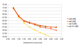
I did some quick measurements, and found that the simple constant revb + direct model seems to be sufficiently valid, and if the revb field really decreases with distance, this effect is not significant because in a small, damped room you will be through the rear wall before the distance is very far from Rx.
I implemented the Rx calculation based on room constant:
Rx=0.141*(G*A')^1/2, where A'=room constant,
A'=ad*S/(1-ad)
S=absorptive area = 1.6*(one f wall + one side wall + one floor).
How well this matches different rooms remains to be verified, but if it is approximately accurate for relatively small, damped rooms it is good enough for this application.
One has to consider that it is really not realistic that the user of this page will go further than to enter basic room data like length, width, height, and approximate RT60.
If someone has measurements readily available, I could check how they match.
Green = calculated using /\.
Attachments
I am putting up a calculator for speaker requirements on my web site, for speaker sensitivity, amplifier power and sound pressure level estimations.
Perhaps in a rectangular room you can use the image method to calculate actual sound field up to an arbitrary number of reflections.
Basically it looks as though the "low ceiling" room (Fig. 8-10) has only a direct field. That is a curious result. Floyd found that the reverberant field dropped at 3 dB per double distance after the direct field dominance. The chart in the attached appears has more like 6 db per DD - essentially the same as a free field.
In the text the author claims about 3.5 dB per distance doubling. Pretty close to what Toole observed. This is all well known in architectural acoustics. Classical formulas are deemed almost adequate for large fairly square volumes with low average absorption. A number of more accurate formulas were developed for less cubic rooms. There are even specialized formulas for rooms with disparate absorption between adjacent walls. Modern "revised theory" assumes some slope to the reverberent field.
In the end it has been replaced by ray tracing computer models. A source at a defined location of a 3D model fires off 10,000 rays. Each one hits surface after surface, losing energy based on absorption coefficient and also distance traveled. An impulse response is created and the necessary acoustical parameters derived from that.
David S.
Hi Dave
I am sorry but when I look at the data in that figure I do not see a 3 dB drop at all. It looks like just extending the direct field down with a straight line would fit the data quite well.
I am quite familiar with ray tracing having started my PhD with it some 35 years ago. I gave up as ray tracing failed to work very well in the modal region because the sound cannot travel along arbitrary rays but is restricted to precise directions dictated by the modes.
I see it is falling at a slightly different slope than the initial free field, and was taking the authors number at face value. Clearly there is some reverberent energy so the far field level must be higher than the anechoic level. The point of the discussion is that the theory of a static reverberent level may apply to large spaces with low average absorption. As we go to deader spaces and more extreme dimension ratios the Sabine view of acoustics becomes less accurate (but this is well known).
Point taking regarding ray tracing and modes. It is still heavily used in architectural acoustics, primarily because the rooms are large and modal behavior is less important. In my brief stint in architectural acoustics, my boss was obsessed with G (room gain over an anechoic space) and early lateral energy, both of which are well modeled with the ray tracing approach.
I was smacked every time I mentioned RT.😱
David
I think there may be little practical benefit from developing very advanced methods to calculate the reverb field in rooms, as it will be difficult to determine accurate data for absorption and absorption area.
A theoretical calculation or simulation is only beneficial if it gives usable information in an easier way than to measure the actual situation.
If we consider the case of a very long, and highly damped room, it is reasonable to assume that the simple model of a constant revb field is no longer valid.
- Status
- Not open for further replies.
- Home
- Loudspeakers
- Multi-Way
- Reverberant spl calculation