Hello all,
at long last I am making a start on my Revox Model 40 stereo amp. I've had the amp about 30 years but many many years ago it fizzed and popped so I put it in the loft thinking one day I would have it repaired.
I think the fizz/pop probably came from the rectifiers as I believe they are prone to that and also they are bulged a little bit. So they are what I will do first followed by a re-cap.
I've uploaded a few pics so people know what I'm talking about.
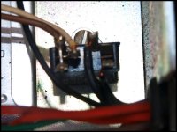
Basically what I need to know is if the replacement rectifiers I have bought are suitable. I'm also puzzled by the smaller rectifier, it has five connections and I'm at a loss as to what to replace that with or should I just leave it alone? Two of the terminals are bridged if that helps.
The amp hasn't been turned on for about 27 years so I am hoping to do this work before plugging 'er in. I have the parts to build a dim bulb tester but sadly do not have access to a variac.
I have done a few re-cappiung jobs so i am reasonably okay with that side of it.
All help greatly appreciated!
Thanks in anticipation
Ian.
Lancaster, UK.
at long last I am making a start on my Revox Model 40 stereo amp. I've had the amp about 30 years but many many years ago it fizzed and popped so I put it in the loft thinking one day I would have it repaired.
I think the fizz/pop probably came from the rectifiers as I believe they are prone to that and also they are bulged a little bit. So they are what I will do first followed by a re-cap.
I've uploaded a few pics so people know what I'm talking about.
Basically what I need to know is if the replacement rectifiers I have bought are suitable. I'm also puzzled by the smaller rectifier, it has five connections and I'm at a loss as to what to replace that with or should I just leave it alone? Two of the terminals are bridged if that helps.
The amp hasn't been turned on for about 27 years so I am hoping to do this work before plugging 'er in. I have the parts to build a dim bulb tester but sadly do not have access to a variac.
I have done a few re-cappiung jobs so i am reasonably okay with that side of it.
All help greatly appreciated!
Thanks in anticipation
Ian.
Lancaster, UK.
Attachments
-
 Front.JPG155.4 KB · Views: 337
 -
 Rectifier 2.JPG221 KB · Views: 193
 -
 New rectifiers.JPG210 KB · Views: 194
 -
 Rectifiers.JPG199.8 KB · Views: 294
 -
 Bottom.JPG205.2 KB · Views: 451
 -
 Top.JPG237.4 KB · Views: 308
 -
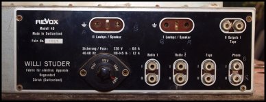 Rear.JPG221 KB · Views: 311
 -
 Rectifier top.JPG187.7 KB · Views: 186
 -
 Revox schem.jpg441.8 KB · Views: 244
Last edited:
The two selenium rectifiers are wired in parallel and can be replaced with a single silicon bridge rectifier. Check the voltage rating on that rectifier - I tend to prefer higher voltage ratings. I'd recommend at least 800V or 1kV for the PIV rating even in relatively low voltage applications.
The filament rectifier can be replaced with a standard bridge with a 100piv rating or better at a couple of amps.
Replace the electrolytic caps as well before powering up!
The bulb will work fine for protection, start with low wattage bulb. (25 - 40W)
The filament rectifier can be replaced with a standard bridge with a 100piv rating or better at a couple of amps.
Replace the electrolytic caps as well before powering up!
The bulb will work fine for protection, start with low wattage bulb. (25 - 40W)
I have the same amp. It is very beautiful.
Had the same issue, of a noisy amp. The new bridge needs to be followed by a resistor to reduce the instreaming current and ensure the transformer keeps quiet.
I replaced the capacitor with a new version of the same (have one still laying around).
A slight capacitance multiplier does charms too.
The preamp section is a marvel.
The power section has a very low amplification.
I had to replace the pots - the balance specifically.
Thanks for the reply.The two selenium rectifiers are wired in parallel and can be replaced with a single silicon bridge rectifier. Check the voltage rating on that rectifier - I tend to prefer higher voltage ratings. I'd recommend at least 800V or 1kV for the PIV rating even in relatively low voltage applications.
Replace the electrolytic caps as well before powering up!
The bulb will work fine for protection, start with low wattage bulb. (25 - 40W)
The new rectifiers I got are 4A 600V. I'd prefer to keep a pair of rectifiers if only to retain the original style/appearance.
Yes, the electrolytics are on the list to do before powering up and I've already got a set of Panasonics.
Cheers,
Ian.
Thanks for your reply. What resisitor do you recommend to put in after the rectifier? Or do I need to do measurements?I have the same amp. It is very beautiful.
The new bridge needs to be followed by a resistor to reduce the instreaming current and ensure the transformer keeps quiet.
A slight capacitance multiplier does charms too.
I am not particularly knowledgable about this kind of stuff. Hoping to mostly replace old with new! I have no idea what a capacitance multiplier is for example.
It is indeed a fine amplifier, when it works! It was my main amplifier for a number of years before the fizz/pop incident. I thought at the time it was something major so I just stashed it away for the future. The future is now here!
Ian.
Ian,
Some comments, if I may.
Unfortunately, that is not feasible.
Rectified voltages rate be higher using silicon, instead of selenium. Some additional resistances are likely needed.
The 6GW8/ECL86 is scarce. It will be difficult enough to source 4 specimens of the same brand, let alone a well matched quartet. The OEM schematic shows truly fixed bias. IMO/IME, that needs to change to a configuration with 4X bias trim pots., to deal with the reality of poorly matched O/P tubes.
Studer used the phono section heaters as resistors in the bias supply. I would bridge rectify the apparently unused 800 mA./12.6 V. winding with 4X 1 A./50 PIV Schottky diodes, cap. filter the resulting "raw" DC and regulate the rail with a 7812 3 terminal regulator, to obtain high quality DC for the phono section heaters. Isolate those heaters totally from the signal circuitry.
In the near future, the 6GW8/ECL86 will go the way of the dodo. Therefore, redesign of what is a fine piece is inevitable. The challenge is reasonably simple to deal with. Eliminate tone controls and use 6BQ5/EL84 O/P tubes. Sufficient 9 pin miniature sockets are already present to support that kind of thing.
Some comments, if I may.
Hoping to mostly replace old with new!
Unfortunately, that is not feasible.
Rectified voltages rate be higher using silicon, instead of selenium. Some additional resistances are likely needed.
The 6GW8/ECL86 is scarce. It will be difficult enough to source 4 specimens of the same brand, let alone a well matched quartet. The OEM schematic shows truly fixed bias. IMO/IME, that needs to change to a configuration with 4X bias trim pots., to deal with the reality of poorly matched O/P tubes.
Studer used the phono section heaters as resistors in the bias supply. I would bridge rectify the apparently unused 800 mA./12.6 V. winding with 4X 1 A./50 PIV Schottky diodes, cap. filter the resulting "raw" DC and regulate the rail with a 7812 3 terminal regulator, to obtain high quality DC for the phono section heaters. Isolate those heaters totally from the signal circuitry.
In the near future, the 6GW8/ECL86 will go the way of the dodo. Therefore, redesign of what is a fine piece is inevitable. The challenge is reasonably simple to deal with. Eliminate tone controls and use 6BQ5/EL84 O/P tubes. Sufficient 9 pin miniature sockets are already present to support that kind of thing.
Ian,
Some comments, if I may.
Unfortunately, that is not feasible.
Rectified voltages rate be higher using silicon, instead of selenium. Some additional resistances are likely needed.
The 6GW8/ECL86 is scarce. It will be difficult enough to source 4 specimens of the same brand, let alone a well matched quartet. The OEM schematic shows truly fixed bias. IMO/IME, that needs to change to a configuration with 4X bias trim pots., to deal with the reality of poorly matched O/P tubes.
Studer used the phono section heaters as resistors in the bias supply. I would bridge rectify the apparently unused 800 mA./12.6 V. winding with 4X 1 A./50 PIV Schottky diodes, cap. filter the resulting "raw" DC and regulate the rail with a 7812 3 terminal regulator, to obtain high quality DC for the phono section heaters. Isolate those heaters totally from the signal circuitry.
In the near future, the 6GW8/ECL86 will go the way of the dodo. Therefore, redesign of what is a fine piece is inevitable. The challenge is reasonably simple to deal with. Eliminate tone controls and use 6BQ5/EL84 O/P tubes. Sufficient 9 pin miniature sockets are already present to support that kind of thing.
Hmm. I expect you're probably right about all that and I do know my limitations. I would consider taking this to someone for repair but think it would be uneconomical hence me wanting to do it myself. I have done some electronic work but my only experience with valves/tubes is modding a couple of SE Guitar amps (Valve Junior, Blackheart BH5) which is why I have come here.
All the valves are the original ones and were working last time it was used although I do appreciate that doesn't mean they will work now! Plenty of ECL86 on ebay at the moment but not cheap.
I'll ponder this for a while before I do anything.
Thanks for your input,
Ian.
I also have the ECL86 scarcity problem. I have 3 matched and 1 old.
The pentode section is same to EL84, so that is correct.
The triode section is a bit hard, but ECC83 should to do well (mu=100).
And yes, you can omit the RIAA section (I did) and reuse the sockets. But now my amp is not in original state anymore 😱
Taking a silicon bridge gives a higher Vb indeed.
My structure is as follows:
replace the GI 3 bridge too I think is a good idea too.
The pentode section is same to EL84, so that is correct.
The triode section is a bit hard, but ECC83 should to do well (mu=100).
And yes, you can omit the RIAA section (I did) and reuse the sockets. But now my amp is not in original state anymore 😱
Taking a silicon bridge gives a higher Vb indeed.
My structure is as follows:
5,5 uF MKP; an inductor (I have not documented what type or exact value, but it was at hand, about 100 ohms DC, somewhere 3-7 H), then a 200 uF cell; then with 3K to the next two cells of 50 uF. My new capacitor was 200+50+50 not 50+50+50.
One trick I did was configuring the pentode part as triode. I did not need more than 5 watts anyway. This works well sound wise, depending on speaker maybe (mine was a Fostex sigma 10).
replace the GI 3 bridge too I think is a good idea too.
Still plenty of PCL86 out there - it may be worth finding some space for an extra filament transformer. See ebay item 370793847380 as an example.I also have the ECL86 scarcity problem..
If I do go ahead what do you suggest I use to replace the G13 rectifier? It has five terminals although two are bridged.replace the GI 3 bridge too I think is a good idea too.
Thanks,
Ian.
Selenium rectifiers are ticking, toxic, time bombs. It is a matter of routine to replace them with modern, silicon, parts.
As for the G13 bridge, 4X 1 A./100 PIV Schottky diodes will be a superior replacement. Unlike PN junction diodes, Schottky diodes don't exhibit a reverse recovery spike. Therefore, Schottky diodes are "noiseless".
As for the G13 bridge, 4X 1 A./100 PIV Schottky diodes will be a superior replacement. Unlike PN junction diodes, Schottky diodes don't exhibit a reverse recovery spike. Therefore, Schottky diodes are "noiseless".
Thanks for that. I understand how to connect the four diodes up but what about the fifth connection? That's the part that has me stumped.Selenium rectifiers are ticking, toxic, time bombs. It is a matter of routine to replace them with modern, silicon, parts.
As for the G13 bridge, 4X 1 A./100 PIV Schottky diodes will be a superior replacement. Unlike PN junction diodes, Schottky diodes don't exhibit a reverse recovery spike. Therefore, Schottky diodes are "noiseless".
Cheers,
Ian.
Thanks for that. I understand how to connect the four diodes up but what about the fifth connection? That's the part that has me stumped.
Cheers,
Ian.
Mihgt be the fifth is a shield connected to earth? I replaced it long ago, no memories left
Thanks for your reply.Mihgt be the fifth is a shield connected to earth? I replaced it long ago, no memories left
The fifth terminal is unmarked but the wire bridges across to the - terminal so I wonder if they both make up the - side of the rectifier. There are only 4 wires attached so hopefully a modern four terminal rectifier will be the same. Detailed information (in a language a simple northern lad like me understands) about the B30C250 is hard to find but here is a picture I found where you can just make out the fifth terminal.
Cheers,
Ian.
Attachments

Thank you. That's exactly what I needed to know.You can safely ignore the 5th terminal.
Ian.
- Status
- Not open for further replies.
- Home
- Amplifiers
- Tubes / Valves
- REVOX Model 40 amp. Need some hand holding please.