I have on my bench, one Rockford T1500-1BD (not T1500-1BDCP). It came in with blown output caps C2016 and C2017, C1015 (main rail cap) was bad, and low collector voltage on Q2010, and Q2012.
I replaced the output caps, the main rail caps, Q2000, Q2001, Q2010, Q2012, U2000, and U2002. I even replaced R2035 with a 1 Ohm resistor as the one that was there is getting super hot. I've yet to do the LM7815 trick that's listed in Perry's tutorial, but I'm just trying to get the amp up and running before I do it...
Now when I power the amp up, the rail voltage builds but does not make it to the output fets. Also the collectors of Q2010 and Q2012 start off at 22.39V but then drop right away to 9.25V. U2002 is heating up and R2035 feed drops to around 3.7V.
Upon my reading in these forums, it was said to replace U2002 and to replace the 74HC74 IC on the BD Output card.. I replaced all of this and the output fets do not get rail to rail oscillation and the gate legs do not get a drive signal.
I have attached the schematic that Rockford has supplied me upon asking - it doesn't include the BD Output Card (I've since asked for the schematic but no reply as of yet).
I have also attached photos of something I saw that was a bit strange - I'm assuming it's because the Q2010 and Q2012 isn't able to supply the 12V to R2035... But when probing the toggle A and B at the anodes of D2000 and D2017 I get different results. The anodes of D2000 have a nice square wave (around 50KHz), but the common cathode is basically DC voltage that sits around 6.4V. When probing D2017, on all pins I get a duty cycling square wave that sits around a volt or so.... When removing D2017, the toggle A and B pins match that of D2000, but the duty cycle on the common cathode remains. Also when removing the U2002, the R2035 voltages stabilize at about 11.38V. I've replaced U2002 again and the same thing happens. The collector voltage drops to about 9.28V on Q2010 and Q2012, R9 gets really hot, U2002 starts heating up, and C1015 starts getting luke warm.
Where do I look next, and what am I missing?
Attachments


Desolder and lift the middle legs of CR1004 and CR1005 and remove U2002.
Does the voltage on all terminals of the regulators return to normal?
Does the drop across R2035 return to normal?
Does the voltage on all terminals of the regulators return to normal?
Does the drop across R2035 return to normal?
I desoldered and lifted the middles legs of CR1004 and CR1005. I also removed U2002.
When powering the amp up (input voltage of 12.6V), I get the following:
Q2010 and Q2012;
Pin 1 - 12.03V
Pin 2 - 22.35V
Pin 3 - 11.84V
U2002;
Pin 1 - 0.623V
Pin 2 - 0.526V
Pin 3 - 0V
Pin 4 - 0.526V
Pin 5 - 0V
Pin 6 - 11.5V
Pin 7 - 0V
Pin 8 - 7.54V
R2035 is at 11.84V
The amp starts off drawing 0.8A. Then after a bit, it jumps to 1.5A and then U2000 starts getting hot.
Then Q2010 and Q2012 collectors drop from 22.35V to 11.73V.....
Q2010 and Q2012;
Pin 1 - 8.01V
Pin 2 - 11.73V
Pin 3 - 7.42
Last edited:
Confirm that R9 is within tolerance.
Remove U2000. Does the voltage still drop on the collectors of Q2010/12?
Remove U2000. Does the voltage still drop on the collectors of Q2010/12?
I've removed U2000. R9 according to the schematic is 30 ohms, and that's what I read.
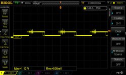
I have attached some waveforms that I think confirm that my 74HC74 is still good.
I powered the amp up, it draws 0.7A and the voltage does not change. It stays OK.
I have attached some waveforms that I think confirm that my 74HC74 is still good.
I powered the amp up, it draws 0.7A and the voltage does not change. It stays OK.
Attachments


It's possible that the driver transformers are shorted. I'm assuming that you've checked all diodes and transistors between the transformers and outputs.
I'd pull them and check the various windings with your LCR meter. I'm not sure what the inductance should read.
Compare the readings of the two transformers.
I'd pull them and check the various windings with your LCR meter. I'm not sure what the inductance should read.
Compare the readings of the two transformers.
I was very afraid that you might say that. I had the gut feeling that the transformer could be the culprit...
So what I did, was I removed D2003, D2004, D2005 and D2006 from the T2000 circuit. Then I removed D2013, D2014, D2015, and D2016 from the from the T2001 circuit. This keeps the drive side of the transformer working, but not the output side. When powering the amp up, right away it jumps to 1.5A of current draw and U2002 starts heating up.
I removed both transformers. I then powered the amp up without the transformers in circuit and on pins 1 and 10 of the transformer pads, there is proper drive.
I reinstalled T2000 and powered the amp up. I got drive to the pads of D2003 and D2004. Once I confirmed that the drive was OK, I tested all the diodes out of circuit again to confirm they are OK. The forward voltage is 0.384V but according to the datasheet that's OK. I reinstalled T2000's diodes, and now I have drive right to the fets for that bank.
When I put T2000's transformer in T2001's spot, the amp starts drawing 1.5A of current and the voltage at Q2010 and Q2012's collectors drops down to 9.35V. When I put T2001's transformer in T2000's spot, the amp then goes to 1.5A and the voltages drop.
I used my LCR meter on both transformers and they both seem to match OK. But by the swapping positions it looks like that transformer is bad. It still doesn't explain why when putting a known good transformer in T2001's position, the amp starts to act up. I removed C2025 and C2026 and tested them out of circuit. They tested OK. I removed C2004 and C2006 and tested them out of circuit, and they test OK as well. I'm going to swap them.
The only thing that I can think of now, is that my testing has possibly destroyed U2002. The Tcase value is only 125 degrees C. I had it as hot as 110 C using my thermal imager, and it may have gotten hotter. Also, it seems as if the 10V supply circuit to and after U2002 isn't able to handle a good transformer even if one is in it. I'm not really sure at this point if I got a dud trace, a bad U2002 (for sure), or some other component on the 10V circuit that's pulling down my voltage. It appears that the INREF circuit gets its voltage from the 10V circuit and then shares it to both LM5110's, so I'm ruling that out as a possibility of being bad. I haven't reinstalled T2001's diodes yet until I can get proper drive out of a working transformer.
My next move is to replace U2002 again, and try to figure out where I'm getting another transformer from. Would you know where to get that transformer from? Also, I've attached a copy of the BD Output Card that I got from Rockford, just in case anyone needs it.
Attachments
tamura pht-102 | Octopart
Search the forum for Tamura PHT-102. That was the part number on the earlier transformers Rockford used.
Thanks for the diagram.
Search the forum for Tamura PHT-102. That was the part number on the earlier transformers Rockford used.
Thanks for the diagram.
- Home
- General Interest
- Car Audio
- Rockford T1500-1BD Power Problems