I have been trying to repair a Rockford T400.4 amp that appeared to have fried all 4 of the power transistors. Previously, the amp was sitting for two years in water, with power hooked up to it (but no remote) (in a trunk that leaked water). There was significant corrosion on the block but the circuit board is visually corrosion free. The block is now corrosion free. I replaced all 4 power transistors, and attempted to replace the six capacitors because of heat damage. Once I powered it up, within just a second or two, all 4 new transistors made a lovely light show and put me back at square one.
In the second it had power before it shorted out, the power light did come on for whatever that may mean. I removed all 4 gate resistors and they all read 35 ohms +/- 0.5 ohm. (I don't know if that is what is required, I can't find a schematic). The original transistors I removed were 75344G and I ordered that exact type online, however the new ones I received and installed were labeled 75344G3 (Not sure if the '3' changes anything). Can another faulty component cause the power transistors to fail?
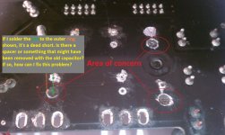
The only other problem I am having is a potentially damaged board due to the soldering equipment I was using when I started this project. I started by using a big soldering gun and poor quality RS desoldering braid. I immediately went out and bought a decent iron, desoldering pump, and Chem-Wik desoldering wick but I fear I did that too late (please see attached picture). If I install the new capacitors and solder both contacts on the bottom side of the board, it becomes a dead short. Is there suppose to be some type of spacer/insulation that allows both contacts to be soldered from the bottom side yet connect to the top side? If so, how can I repair this? (Most places on this side of the board seem to have B+ on the top side and ground on the bottom or visa versa).
Please see attached photos
Any assistance would be greatly appreciated. I am a mechanical engineer and my knowledge of electronics (circuit boards particularly) is rather limited, but I am trying.
Thanks
In the second it had power before it shorted out, the power light did come on for whatever that may mean. I removed all 4 gate resistors and they all read 35 ohms +/- 0.5 ohm. (I don't know if that is what is required, I can't find a schematic). The original transistors I removed were 75344G and I ordered that exact type online, however the new ones I received and installed were labeled 75344G3 (Not sure if the '3' changes anything). Can another faulty component cause the power transistors to fail?
The only other problem I am having is a potentially damaged board due to the soldering equipment I was using when I started this project. I started by using a big soldering gun and poor quality RS desoldering braid. I immediately went out and bought a decent iron, desoldering pump, and Chem-Wik desoldering wick but I fear I did that too late (please see attached picture). If I install the new capacitors and solder both contacts on the bottom side of the board, it becomes a dead short. Is there suppose to be some type of spacer/insulation that allows both contacts to be soldered from the bottom side yet connect to the top side? If so, how can I repair this? (Most places on this side of the board seem to have B+ on the top side and ground on the bottom or visa versa).
Please see attached photos
Any assistance would be greatly appreciated. I am a mechanical engineer and my knowledge of electronics (circuit boards particularly) is rather limited, but I am trying.
Thanks
Attachments


Solder at least one filter cap across the B+ and ground terminals before you power it up again.
The gate resistors and the driver transistors can fail when the power supply FETs fail.
If you haven't done so yet, read the basic amp repair page in its entirety (link in sig line below) before you do anything else.
The gate resistors and the driver transistors can fail when the power supply FETs fail.
If you haven't done so yet, read the basic amp repair page in its entirety (link in sig line below) before you do anything else.
That repair page has been really helpful so far, I would like to purchase the full tutorial if I can get the money to do so.
Do you think my gate resistors are OK and safe to put back on at 35 ohms?
I would like to clarify what I am about to do and make sure this is right before I fry another component (took over a month to get the last transistors shipped here, thankfully I bought twice the amount I needed). I should replace the 4 transistors again, install NO capacitors on the board BUT solder one across the power terminals, solder the resistors back on, and power it up with 10 amp fuses on everything?
Check the resistors? IF they're within tolerance, they don't need to be replaced. They were likely 34 ohms.
Where did you order from that took more than a couple of days to get to ohio?
The capacitors with the missing pads are essentially connected across B+ and ground. Connecting them to the damaged connections may not result in a real connection to the traces.
Don't forget to clamp the transistors before applying power.
I ordered my replacement transistors off ebay.com from some company located in Hong Kong because that was the only place I could find them. Shipping took about 3 weeks. Here is the link if you are curious: 10pcs HUF75344G3 75344G Original Fairchild N Channel Ultrafet Power MOSFETS | eBay
In the attached image, are the circled components the driver transistors?
Is it possible (or necessary) to test the IC and the transformer before installing the new transistors and capacitors?
In the attached image, are the circled components the driver transistors?
Is it possible (or necessary) to test the IC and the transformer before installing the new transistors and capacitors?
Attachments

No those are the rectifiers and regulators.
The driver transistors will be on the upright board labeled PWM, right next to the transformer.
The driver transistors will be on the upright board labeled PWM, right next to the transformer.
Unless you know DEFINITIVELY that a seller is legit on ebay, never purchase semiconductors there. There are far too many sellers selling counterfeit parts.
Reputable sellers:
http://octopart.com/partsearch#search/requestData&q=huf75344g
No. Those are regulators and rectifiers.
The drivers are likely on the PS driver board. Does this amp use the board below?
Reputable sellers:
http://octopart.com/partsearch#search/requestData&q=huf75344g
No. Those are regulators and rectifiers.
The drivers are likely on the PS driver board. Does this amp use the board below?
Attachments

Perry, Yes I have that exact board on this amp. I will go ahead and purchase new transistors from the site you listed.
Order at least 10 each of the MMBTA06 and MMBTA56. Q103 and Q104 commonly fail when the power supply FETs fail. Those transistors are good subs for the drivers on that board.
I'd suggest digikey or mouser.
I'd suggest digikey or mouser.
I will get all those ordered this evening. I ordered 4 transistors from the site you listed earlier, hopefully that will be enough. I greatly appreciate the help.
Unfortunately no good news yet. I just received all of the components I ordered from Mouser and soldered everything onto the board. On the 'AB Power Supply' chip I replaced Q103, Q104, Q105, and Q106 and everything appears to have gone well. I did notice that the original Q104 was visually fried and cracked in half. I put the gate resistors back on, soldered on the new power transistors, and got the capacitor situation resolved.
When I tested it:
I hooked up just ground and B+ with a 10amp fuse and all was well. As soon as I hooked up the remote wire (also with a 10 amp fuse), the fuse on the B+ blew. I tried again with a 20 amp fuse on the B+ and it also blew instantly. Any suggestions?
When I tested it:
I hooked up just ground and B+ with a 10amp fuse and all was well. As soon as I hooked up the remote wire (also with a 10 amp fuse), the fuse on the B+ blew. I tried again with a 20 amp fuse on the B+ and it also blew instantly. Any suggestions?
Attachments

There's no reason to use a 20 amp fuse. An ATC10 or ATC15 should be plenty.
Disconnect the B+ (leaving only ground and remote connected). What is the DC voltage measured for each power supply FET with the black probe on leg 3 and the red probe on leg 1?
Disconnect the B+ (leaving only ground and remote connected). What is the DC voltage measured for each power supply FET with the black probe on leg 3 and the red probe on leg 1?


It appears that you have an open gate resistor or a broken connection between the driver transistor and the gate for #3.
One of the gate resistors seems to be damaged. There was no continuity between the leg of the resistor and the power transistor. I desoldered and tested it and was barely able to get a reading of 34.2 ohms if I pressed on it just right. I soldered it back on and I had continuity, then proceeded to test it with just ground and remote hooked up and suddenly there was no continuity again. I am going to order 4 new gate resistors if I can find the right ones. Do you know the part number of the gate resistors? The others read 35 ohms.
I think something else may be going on. I switched some of the gate resistors around and no matter which one I put on that power transistor (#3), it acts up once I add ground and remote power. There is continuity between the resistor and leg 1 of the power transistor when no power is present, then no continuity once powered up. the resistor is still reading the proper ohm load and there is voltage at the resistor, but not on the other side that connects directly to the power transistor. The 'bad' gate resistor works fine on a different power transistor. I tried turning the gate resistor around, thinking that it might have been acting like a diod, but no different.
It seems that one of the brand new power transistors from Mouser is bad. I swapped two of the transistors around and the problem followed it.
Well I removed all 4 power transistors from Mouser and the one that was acting up was a dead short on all terminals (I'm guessing it came that way). I replaced them with the extra transistors I had from China and everything works!! and no fires!! Voltage across all 4 is exactly the same at 4.87volts. I feel like I should still replace them with ones from a reputable dealer since I don't know what the China ones will do once I apply a load.
Perry thank you so much for all of your help and knowledge. If you have a web site that accepts feedback to promote yourself or your business I would be happy to add a post.
Perry thank you so much for all of your help and knowledge. If you have a web site that accepts feedback to promote yourself or your business I would be happy to add a post.
- Status
- Not open for further replies.
- Home
- General Interest
- Car Audio
- Rockford T400.4 repair help