Hi guys I failed miserably on a teac amp recently and decided to try this rotel out.
The problem is the sound on both channels is distorted. you have to turn it up max and all you hear is crackles on speakers and via headphones sounds half decent but at high volumes struggles and starts distorting.
I have service manual and its really confusing. The voltage seems right for one side but the main voltage is wrong but everything checks out ok?!?!
The part is also not the same on sm is 802 bridge diode. but its actually an PBPC803 installed but it checks out ok. everything there seems to check out diodes, resistors, caps. sm manual states 41v but im getting 36v. on the other end it states 17v and i am getting 17v
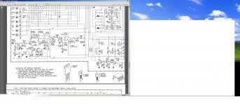
Attachments


Don't tell me - an Ebay "bargain"?
The +/-17V supplies are for the preamp. They are broken down from the raw +/- 41V DC that supply the power amplifiers, by voltage regulators Q903,4. If you still have +/- 36V there at the collectors of Q903,4 , you would expect these would have no trouble still maintaining the correct +/-17V output for a light load like the preamp and other ICs. The measurement points are from common ground to each collector there.
With the main supplies down to 36V though, you still have a serious fault, like possibly shorted power output stage. Given the symptoms of scratchy, rough and low level output, it seems very likely the case. Note - once you hear this sort of problem, don't persist with trying to get power out of it - remove the speakers and any input leads, turn down the volume fully and measure any DC voltage (offset) across the output terminals of both channels. Obviously, they need to be connected to the amplifier by the speaker selector being in the appropriate position or you can connect direct to TP4 and ground if the amplifier is opened up. If your DVM is better than junk, it should have a lowest range about 2V so that it can resolve only millivolts (mV), which you would expect to measure here. A reading somewhere between +or- 0-50 mV would be acceptable for either channel.
On the other hand, if you measure volts or even lots of volts, you do have some work ahead of you and likely a need to replace some expensive parts that could be hard to find, since fakes and off-spec. copies abound for the power transistor types fitted in this amp.
As a piece of advice from someone who has caused almost as much damage to amps as fixed it, use clip leads or IC hooks with multimeter leads to avoid slipping and shorting the live circuits under test. It's very easy to destroy a lot of work and $$$ in a few milliseconds with a loose pair of test probes while you trying to read the meter. So - let's have some tests rather than guesses to get started. 😉
Hello Ian it was a bargin actually lol. I bought it for £20 about 6 months back. It had so many black gate caps init I thought to my myself cant go wrong even for parts!
As you can see right have very little dc off set with the bias turned all the the way down and left has a little more. I think the setting is millivolts. so right is 0.004 v and left is .040 v
The one things I did notice was when headphones connect dc off set set at highest rating I could hear half decent sound. When dc off set was set lowest like now I could only hear distortion via headphones. Alo I get 0 volts across the test terminal for bias adjust, adove dc adjust. dc off set adjust is closest to big yellow cap.
Attachments


Last edited:
Until the amplifier DC conditions and supply voltages are correct, don't try to use audio to test. It can only exacerbate problems and add to replacement part problems and costs. Getting sound by increasing offset voltage is rather pointless and you may even hear sound direct from the driver transistors simply delivering current via any shorted output transistor junctions, but this isn't productive and will only end in more parts failures.
Are fuses F601,2 making good, firm contact withe holders? Have you measured the supply to Q903,4 collectors yet? 'Better look at the voltage on the collectors of the output transistors too (that's the centre pin and/or the metal backplate).
Simply test the marked voltages on the schematic that are associated with the DC side of the power supply and both output stages. It's likely there will still be differences between channels and it's better to know what they are. If you have one channel working, it always makes a good reality check or rather, a comparison for correct operation, for the other. If you see any clear departures from the spec or differences as suggested, please tell us.
Then check Emitter to Collector voltages for E-C shorts and B-E diode voltages of the output stage (all working transistors should measure ~0.7V Vbe, either polarity) of Q626-634 and drivers Q622-625. Note that the output transistors are in parallel pairs so a short in one transistor measurement will only be repeated in the parallel device. Eventually you may need to remove these transistors to test individually if there appear to be shorts.
One warning that is relevant to modded "accident amps" - the input caps may have been removed and/or shorted. This can cause disasters due to unwise input connections. Check you still have DC blocking caps at the inputs.
Take care with probe measurements 🙂
Plus...
The fried 3W 1k resistors that limit bias current to the drivers, R683-686 may appear damaged but could still be OK. Coatings shrink and peel more easily from larger diameter parts and this may not be quite the disaster it looks.
The fried 3W 1k resistors that limit bias current to the drivers, R683-686 may appear damaged but could still be OK. Coatings shrink and peel more easily from larger diameter parts and this may not be quite the disaster it looks.
Hi Ian,
Fuses are good and firm.
Q903/4 have 36v going in and 17 and 17.5 as per sm manual. its suppose to be 41v but everything else checks out.
None of the channels work! pretty much same level of distortion.
There is no shorts on the transistors I checked them once before.
I also suspected the 3w resistors but they seem fine. As far as I know. Resistance checks out.
The bridge diode gives me >560 reading on diode setting.
If it is a power issue then it must be transformer or bridge diode. There are some small caps 0.01uf under the diode. I cant test them (I dont think) they seem ok. The large caps also measure 36v also the main diode at outputs! :?

I just measure the transformer and it said 27.1v! the markings on the unit itself say 28.3v. so it was never going to be 31.7v input ac!?!?
Correct, the transformer is either a replacement from a similar amplifier (it's not a standard type with that voltage rating) or a change not shown on that issue of Rotel's service manual. (ex - Hifiengine, by the appearance) I suspect the former and I suspect there have been other repairs before too. The specification for this model seems to change from one retro reviewer to another on the net, so there is confusion as usual among those who like to recycle audio systems.
However, that won't affect operation other than the maximum power available before clipping, which is seldom a problem unless you live in a large house or have free reign to play loud. You have +/-36V which is still fine and should deliver 50W/8R or thereabouts unless it suddenly disappears when you connect a load to the amplifier, which I doubt is the basic problem but you could recheck these voltages at the output stage when the amplifier is connected to the speakers (as briefly as possible) to dispel notions about the transformer being faulty.
I'd be interested to know how you tested the output transistors as all being good, unless you had removed the paralleled transistors to test them thoroughly for shorts or open circuits. Neither can you properly test a diode bridge without disconnecting the transformer but from the balanced rail voltages, it appears to be OK.
Again, were all the Vbe measurements for these output transistors and drivers aprroximately correct? What did you measure for Vce of the output transistors (yes, that means the voltage between Emitter and Collector). Now take a look at the markings on those transistors - what brand or logo are they? Are they poorly laser etched, printed or foil marked? Any other marks like a date/batch/grade code? Are the heatsinks electrically isolated from the circuit? (the anodizing is an insulator so make contact with a bright aluminium surface, such as a hole or worn edge).
Not sure what you mean by "..main diode at the outputs...". Surely it has a part no. reference.
Assuming there weren't actually any problems with the output stage, we'd really need to see what signal you have before it so that we can systematically test the amplifier. You need an oscillosope and signal generator or at least an audio millivoltmeter for that and you may understand that a DMM is not really adequate for other than DC checks on power amplifiers and components. There is little available in a meter alone to conclusively test operation so you are left with systematically going through the smaller transistors for C-E shorts and Vbe checks.
The list of possibilities goes on without more specific feedback but I notice you are also pursuing this matter concurrently on another forum and perhaps hedging your bets. Make up your mind and follow through on one set of advice or the other.
Hello Ian, dont be mad I'm just trying all options to resolve this. Everyone seems puzzled by this. I am really exited about finding out what the issue is.
I did take out ALL transistors and bridge diode there were no shorts and everything seemed ok to my limited knowledge, I'm pretty sure I was thorough. The main transistors the big ones seem all original. From what I remember they all seemed high quality originals/replacements of same.
By main diode I meant bridge diode. The outputs measured 36v in circuit.
I still get no voltage reading on bias adjust 0v.
I'm not at all mad about your wanting more than one opinion on the problems but other dialogue inputs that are unseen here probably influence your replies and make it puzzling to follow where your ideas come from or why you seem to ignore some parts. Still, that's your business but just say if you haven't got around to doing some things yet, perhaps have a new suggestion from another party or you are having trouble following what was asked etc. Otherwise, I could conclude that you are distracted by other matters or don't wan't to try some things out.
Have you measured the Vbe voltages yet, either as voltages measured in-circuit with the amplifier working or as B-E diode drops measured with the meter?
Another question for you: Do you have another amplifier of any size - even headphone size that could be used to trace the audio through the amplifier? It needs to have a sensitive input of around 10k impedance and a volume control, like a pre-amp of some description. With no oscilloscope, you must have some way of testing the presence of signal along the signal path to verify whether there is something yet untested that prevents normal operation. Otherwise, it's just shooting blind and doing more damage by removing, testing and refitting parts more than is good for the PCB.
The alternative is to print a copy of the schematic and clearly write on it or list all the transistor terminal voltages so that the circuit can be analysed. I have to confess that there are others here, more competent to do this than I, particularly where things get complicated in unfamiliar circuits. No problem though, we do help when enough data is available and set out logically. 🙂
There s all possible voltages on the service manual...
Rotel RA-940 Manual - Stereo Integrated Amplifier - HiFi Engine
As pointed by Ian you should measure and post the voltages , without those values it s impossible to help otherwise than with wild guesses...
Rotel RA-940 Manual - Stereo Integrated Amplifier - HiFi Engine
As pointed by Ian you should measure and post the voltages , without those values it s impossible to help otherwise than with wild guesses...
Guys I willing to do what ever! but understand if the sm manual is wrong Im only getting 36 volts out of bridge diode. and 27 volts from transformer. sm states 31v from transformer and 41v from bridge diode. if 36 is acceptable then the issue lies else where.
i have already tested ALL transistors off board they seem fine unless in circuit they behave different. All main transistors have 36v going in from main. Suggesting they are getting the voltage setout by the bridge diode.
I like the idea of testing the circuit in another amp, thats easiest for me I think. i did conect small speaker to volume control and it did not have distorted sound!
I will test all voltage going into transistors and post results.

Guys I willing to do what ever! but understand if the sm manual is wrong Im only getting 36 volts out of bridge diode. and 27 volts from transformer. sm states 31v from transformer and 41v from bridge diode. if 36 is acceptable then the issue lies else where.
.
Supply voltage is OK as the amp is specced at 40W/channel...
The 28V value is not the good one, either it s the driver that is attached to this resistance that is faulty, or it doesnt get the good command voltage.
Could you check visualy the value of R659/661 and R660/662..?.
If value is 2.2K as in the schematic unsolder a end and measure them to see if they are not in open circuit, of course with the amp being off.....
the resistors look good they all measure 1.42k in circuit. sm states 2.21k. I can unsolder tomorrow and check.
Visually checking the value of a resistor means to check the marked value, i.e. the colour code bands, beginning at the end where bands are closest together. e.g 2.2k 5% is red-red-red--gold. 2.2k 1% is red-red-black-brown--brown etc. depending whether 4 or 5 band codes associated with typical carbon or metal film types, are used.
4 Band Resistor Calculator | Electronics and Electrical Engineering Tools | EEWeb Community.
In the above Wiki, you can select any number of bands as they appear on your resistors.
4 Band Resistor Calculator | Electronics and Electrical Engineering Tools | EEWeb Community.
In the above Wiki, you can select any number of bands as they appear on your resistors.
Last edited:
This amplifier topology is somewhat weird with its serial triple differential untill one notice what they actualy designed...
Open loop gain is about 52db and NFB ratio is only 20db for a 32dB total gain, open loop bandwith is 20KHz by the virtue of two parraleled 2.2K resistors that load the "VAS" to the ground, quite a brute methode given the resulting 30mA peak currents..
If it s serviced successfully it would be insightfull to get some feedback (!!) about its sound signature...
Hi Wahab. Yes, there are a number of design features here that are now frowned upon. The ouput stage itself is said to keep the drivers operating in class A but is wasteful and described as no better at this than standard EF designs, by D.Self. It had also been used in the Lohstroh and Otala amplifier and Pioneer M3. Given the number of typical UK components and varying typeface, I suspect this is one of Stan Curtis' Rotel models for the European market.
- Status
- Not open for further replies.
- Home
- Amplifiers
- Solid State
- Rotel RA-940BX distorted sound