Hello all,
I have a Rotel RB-985, 5 channel amp which is quite old. But considering pairing it with my Yamaha RX-A6A for my 7.1.4 setup to offload the built in amp
However one of the channels(front lev) is making a sine wave/varying sound output, when nothing is connected to the input. Link to audio noise:
https://whyp.it/tracks/253536/rotel-rb985-noise-on-left-ch
I'm quite handy and open to try to solder / replace some of the electronics. But unsure where to start. Any advice?
Best Regards
Joakim
Attachments

That channel seems to be oscillating badly. An oscilloscope can check the full scope of the frequencies/amplitudes involved. If the oscillations disappear when the RCA input is shorted, check the negative feedback components and input stage transistors. I'd start with a check of the DC operating parameters; these should be clearly stated in the schematic diagram. The photo you attached is of poor resolution. Post the higher-resolution, in-focus, well-lit photos, and we might be able to spot something with the naked eye. Show us the PCB underside as well...
Thank you for feedback. I dug some further yesterday and attached the new pictures I took and the service manual(although not the best quality).
The oscillating does not happen if the input wire is shorted or if its disconnected from the terminal. I do not have a oscilloscope, but considering buying a cheap one from AliExpress\Amazon to get started if required.
I've measured and BIAS voltage on the 4 other channels are within the manual specification(5mv). But on the Front Left channel(measuring points TP401-TP402) which I have issues, there's 0mv and its not affected if i turn the VR401 clockwise or counterclockwise.
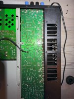
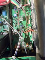
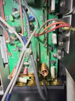
Seems the layout of Right Surround and Right Front PCB are identical to the Left Surround and Left PCB(I only have issues with the oscillating on the left channel). Some of the smaller caps(blue) on the PCB have been replaced as they look newer and are not the same as on the other pcb(see C511, C512 - C411, C412) . Some of the transistors might be resoldered by the looks of it(Q414, Q412 - Q415, Q417 - Q416, Q414).
Seems numbers starting with 4 is related left channels, 5 to surround left channel(same PCB).
This has been quite a steep learning curve for me. yesterday I did not even know what BIAS was. I would need help to continue to troubleshoot this to get it sorted, what should my next steps be?
The oscillating does not happen if the input wire is shorted or if its disconnected from the terminal. I do not have a oscilloscope, but considering buying a cheap one from AliExpress\Amazon to get started if required.
I've measured and BIAS voltage on the 4 other channels are within the manual specification(5mv). But on the Front Left channel(measuring points TP401-TP402) which I have issues, there's 0mv and its not affected if i turn the VR401 clockwise or counterclockwise.
Seems the layout of Right Surround and Right Front PCB are identical to the Left Surround and Left PCB(I only have issues with the oscillating on the left channel). Some of the smaller caps(blue) on the PCB have been replaced as they look newer and are not the same as on the other pcb(see C511, C512 - C411, C412) . Some of the transistors might be resoldered by the looks of it(Q414, Q412 - Q415, Q417 - Q416, Q414).
Seems numbers starting with 4 is related left channels, 5 to surround left channel(same PCB).
This has been quite a steep learning curve for me. yesterday I did not even know what BIAS was. I would need help to continue to troubleshoot this to get it sorted, what should my next steps be?
Attachments
-
 underside- left pcb-closer2.jpeg709.6 KB · Views: 36
 -
 underside- left pcb-closer.jpeg735.3 KB · Views: 39
 -
 underside- left pcb.jpeg660.8 KB · Views: 37
 -
 right+surr channel.jpeg587.1 KB · Views: 36
 -
 pcb-mounted-horizontally-behind-front-of-amp.jpeg353.6 KB · Views: 42
 -
 left+surr channel-2.jpeg653.8 KB · Views: 48
 -
 left+surr channel.jpeg623.3 KB · Views: 39
 -
 left+surr channel 10.jpeg512.8 KB · Views: 38
 -
 left+surr channel 9.jpeg625.2 KB · Views: 39
 -
rotel_rb-985_parts_sch.pdf2.5 MB · Views: 35
-
 left+surr channel 3.jpeg561 KB · Views: 36
 -
 left+surr channel 4.jpeg602 KB · Views: 44
 -
 left+surr channel 5.jpeg677.5 KB · Views: 36
 -
 left+surr channel 6.jpeg712 KB · Views: 38
 -
 left+surr channel 7.jpeg611.3 KB · Views: 39
 -
 left+surr channel 8.jpeg721.4 KB · Views: 42
Does the affected channel play music like the other channels? Use some cheap/spare speakers to test this....
The amplifier can oscillate if the power supply rails' decoupling capacitors have too large or too small capacitance, i.e., not as intended by design. So, the first thing would be to make sure that the replaced capacitors have the same capacitance as the other (original) capacitors.
I managed to put together the two schematic sheets - see below. You can see which transistors set the bias by varying their base-emitter voltages. Make sure that all components are correct and that they measure correctly (by comparing with one of the other identical, good-working channels). I circled these components in red.
The OPAmp is used as a protection and negative feedback amplifier. Hence, it is important that the IC and all the surrounding components are of the correct value and working correctly. I circled these components in blue.
The faultfinding shouldn't be difficult, but you do need some knowledge and a bit of experience, a multimeter and an oscilloscope. Also, when checking/comparing values/voltages/currents, you could short things out and/or damage the PCB tracks, which can result in an unpleasant bang. I think it would be best to seek help from an electronics engineer/serviceman.
Thank you. Yes the channel does play music, but you can hear the noise when music is on lower levels and I do feel the channel is underperforming and distorting
I will do some more measurements and report back.
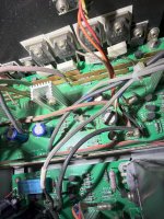
One thing I have found is the Q410 seems to be turned 180 degrees in the wrong direction, see attatched picture as against the markings on the pcb. Unsure if this migh just be wrong print


I will do some more measurements and report back.
One thing I have found is the Q410 seems to be turned 180 degrees in the wrong direction, see attatched picture as against the markings on the pcb. Unsure if this migh just be wrong print
Just so happens I am buying one of these Rotel RB-985's this coming weekend. The seller said the center channel does not work. I plan to open the amp and do a complete inspection, testing and repair. From your photo's it looks clear that the amp has been repaired before. And yes I would say that Q410 silkscreen is correct. And the transistor is either a substitute with reveres pinout. Or is installed backwards! Also the blue electrolytic capacitors look the be replacements. I would recommend that you do not under any condition turn the amp on again. I have all of the test equipment and decades of experience to help you out.

Hi Guys
Here is an update for you on the Rotel RB-985 I got last weekend. After over a month of effort trying to buy this amp. I finely got it home last Saturday and opened it up on Sunday. The seller said the center channel did not work. I have only removed the top cover so far. Then did a quick visual check before turning it on. I had found no signs of repairs, thermal stress of parts or bad capacitors except one electrolytic on the center channel PCB. When I powered up the amp the protection LED's responded normal. But when I powered the unit off. The individual protection LED's turned off in a non consistent pattern. My next step will be to remove the DC power supply fuses from the center channel amp PCB. Then test the remaining four channels and power supply. One thing I found on my visual inspection is the 4 main power supply filter capacitors that are mounted horizontal from the front panel. All have a noticeable crown bulge on them! But they are all the same amount? I will test the DC leakage on them when I have time. But first just look at AC ripple waveforms with no signal applied. I understand from my experience how good this simple test can be. NOTICE! For the little amount of time I have compared the schematic to the parts list. I have found many parts reference designation and part numbers incorrect. I suspect this is a disconnect between the fabrication house and Rotel engineering schedule to market issues. Since the Rotel RB-985 MKII was the next model of the evolution of marketing. But the specs Rotel RB-985 MKII suck from what I see! We got a true gem here. More updates soon. Cheers, Chris
Here is an update for you on the Rotel RB-985 I got last weekend. After over a month of effort trying to buy this amp. I finely got it home last Saturday and opened it up on Sunday. The seller said the center channel did not work. I have only removed the top cover so far. Then did a quick visual check before turning it on. I had found no signs of repairs, thermal stress of parts or bad capacitors except one electrolytic on the center channel PCB. When I powered up the amp the protection LED's responded normal. But when I powered the unit off. The individual protection LED's turned off in a non consistent pattern. My next step will be to remove the DC power supply fuses from the center channel amp PCB. Then test the remaining four channels and power supply. One thing I found on my visual inspection is the 4 main power supply filter capacitors that are mounted horizontal from the front panel. All have a noticeable crown bulge on them! But they are all the same amount? I will test the DC leakage on them when I have time. But first just look at AC ripple waveforms with no signal applied. I understand from my experience how good this simple test can be. NOTICE! For the little amount of time I have compared the schematic to the parts list. I have found many parts reference designation and part numbers incorrect. I suspect this is a disconnect between the fabrication house and Rotel engineering schedule to market issues. Since the Rotel RB-985 MKII was the next model of the evolution of marketing. But the specs Rotel RB-985 MKII suck from what I see! We got a true gem here. More updates soon. Cheers, Chris
- Home
- Amplifiers
- Solid State
- Rotel RB-985 - noise sine wave/varying sound output