Hello all,
First post, long time lurker. I've been building for about 12 years with varying amounts of success. I started out with trying the different types of enclosures from sealed/ported to some quarterwave and OB stuff. Then I found out about miniDSP and fell down the active rabbit hole for like 7 years. Here are some pictures of one of my builds. Recently the GR Research youtube channel got me interested in actual passive crossover design and measurements and that's pretty much where I am now. I converted some of my active builds to passive using measurements and software for the first time. Then did some other upgrades to speakers for some friends.
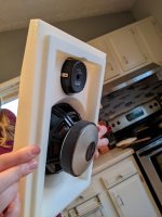
Recently I decided I would try to make a small bookshelf speaker that could come-to-market as an exercise, not an actual goal. This being my first post and all, I want to stress that I'm fully aware a speaker I'm making isn't going to show up in stores, ever. I'm not even trying to sell this pair, I'm giving them to my cousin. Anyway, here was my attempt at making a cheap (sub $1000 MSRP), small, bookshelf speaker. The project kind of snowballed and ended up not being very cheap after getting the MDF CNC'd on the second attempt and adding a second passive radiator. The drivers are the SB Acoustics SB13PFC25R-08 5" Paper Cone Woofer and the SB29RDNC-C000-4 Neo Magnet, Ring Dome Tweeter.
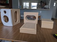
I used .5" MDF on the prototype and a single passive radiator (rear mounted). The bass wasn't very extended and the cabinet had a good bit of vibration on the sides, despite having a brace between the tweeter and woofer that touched 4 walls.
I moved to .75" MDF and two passive radiators to hopefully boost the low end a little bit (I'm guessing this sounds funny to better designers). I didn't succeed with the bass extension in the end. When selecting the woofers I wasn't sure if I should trust the low frequency part of the plot, but after completion I believe I have my answer.
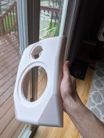
The front baffle is 3D printed and bonded to the MDF with resin. Printing allowed way more freedom in angles and features since I'm not very good at woodworking. They were printed at 25% infill and weigh just under 500g each. On a small build like this, I would definitely 3D print again.
How do they sound? I was very surprised at how detailed and accurate these things turned out. These $35 woofers are an insane value and I will definitely be using more SB Acoustics drivers in future builds as a result. I really enjoy the tight bass that they are able to produce. They only reach down to 60Hz, but there is noticeable drop-off below 100Hz. Bass strings are very articulate. They are fun to listen to after a healthy bit of bass boost on the amplifier side. Imaging and transparency are very good. I really like the sound of this tweeter and it's small faceplate.
Specs:
60-20,000Hz +-2.5dB
~91dB efficiency (this seemed high to me, and I haven't measured this before so I may have done it wrong. I used my o-scope to set Vrms to 2.83v at 1000Hz and did a sweep at that level)
8ohm nominal, 5.3ohm minimum
Internal volume: 9L
External dimensions: 8" wide, 11.25" tall, 11" deep
Material costs:
Drivers: 71.60x2 + 34.70x2 + 35.70x4 = $355
Crossovers: $111
3D Print material: $15
MDF: $25 (can be cut from 1 quarter sheet)
Total: $506
Takeaways:
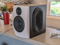
- They are a good speaker, probably my best so far in terms of natural sound. BUT, I'm not sure anyone would want it in the $1000 range without more bass extension.
- It's hard to make a cheap speakers without auditioning a bunch of drivers and prototyping a lot of enclosures.
- Passive radiators sound really good but add a large percentage of cost, duh.
- It's even harder to make a cheap speaker when they have to look good. These look OK in the pictures, but could not be sold in mass market they way they are.


Vituixcad allows you to select a passive woofer, not sure it allows multiples.
I think maybe try differing Tweeter attenuation values as a a quick solution, see what you think to the bass quality when you have lowered the treble level by 1, 2 or 3 dBs.
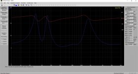
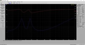
I haven't experimented with Passive radiators yet, but what happens if you start filling the internal volume by using a block of wood, or other suitable sized object, and check against the impedance profile. Do you get the two basically equal peaks of a reflex design and at what frequency ? Could you post a shot of the current impedance profile?
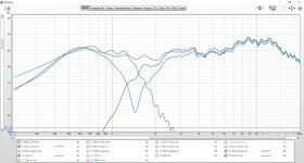
What does the unwindowed frequency response look like, could you also post that?
I haven't tried filling in the volume. Can you walk me through what you're looking at on the impedance curve if it's not looking right?
I found out about Vituixcad after this project and have switched over. I'll look for the passive woofer modelling. I was using winISD.
I found out about Vituixcad after this project and have switched over. I'll look for the passive woofer modelling. I was using winISD.
Attachments
Last edited:
Thanks for posting the info.
Hmm, the frequency response for the bass doesnt look like the you have passive radiators contributing a lot.
I am making assumptions here but maybe the midbass on its own reflex tuned may give more. bass?
Typically in a reflex you would expect a symmetrical U shape, with the bottom of the U showing where you you have good damping, indicating control over that frequency range. A wide bottomed U would be good damping and good power handling, in terms of limiting driver excursion in that range. Unfortunately I haven't a clue regarding how reflex and Passive radiator map against each other. I learn by experiments, and I haven't done this yet.
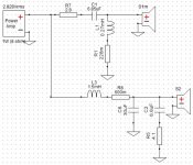
Looking at your frequency response and ignoring the bass end I would probably increase the inductor value at least 1 or two more steps and see if that doesn't help with the perception of bass. Naturally you may have to do the tweeter Xover to adjust to the new values and keep your null and aim for a gently downward shape.
Where was the frequency measurement made? Indoors or outdoors ?
I have attached a reflex impedance for another 5" driver as an example for a reflex tune that sound good to me.
Attachments
I was thinking along the same lines on the first enclosure I made. I cut another piece of wood and covered the radiator cutout and gave it a standard port. The impedance plot of that ported enclosure is below. The bass response seemed the same at least enough so that I didn't pursue it any further. I don't think I saved any of the frequency response measurements.
This was my first build with passive radiators so I don't have a good understanding either.
Measurements were taken indoors about 60" from the floor and not near any walls.
This was my first build with passive radiators so I don't have a good understanding either.
Measurements were taken indoors about 60" from the floor and not near any walls.

flipsnshyt,
Looks like you put in so much work into building a nice looking and well-made cabinet, I wish you would use better quality mid-woofer drivers from SB Acoustics driver, the Textreme and Satori drivers, if not at least the ceramic range of drivers. I believe that will improve the performance of the speakers to the next level. Just a suggestion.
Hi flipsnshyt
Nice build.
Firstly, have you used any extra weight for the passives?
See sim here, you'll get ca 10 Hz lover 3 db point if you add 40g to each passive radiator. Think this will help a bit.
Secondly I think as is also hinted by raymondj, your are running the tweeter too hot. This will give a light sound with less bass.
You should try aiming af a lightly sloping freq from 1 to 20 kHz by -3 to-6 db (normally described as a house curve).
Also maybe try to crossover a bit higher e.g. 2.5 kHz, for higher power handling and probably more even directivity (check directivity by measuring e.g. 30 and 60 dg angle)
Could you share the VituixCAD files, we could give it a go.
I'm a full supporter for passives, but I would think for a build like this I would have gone for just vented ... you could actually have had a little better bass I think, and the cost as you say would be much better 😉
PS. and why 2 passives per speaker ... one would have more than enough Sd + excursion I think ....
WinISD; Magneta = passive + 40g, Green ported, Yellow, Passive without extra weight
Attachments
Your info on the measurements is good to know, the low frequency data allowing for the quasi anechoic measurements will be representative and backs up how you have described the sound.
Baldin has given more insight, and his graphs show you can get decent bass output down to 40Hz or so.
If you want to, possibly try one subwoofer and tune with mass. You can mount penny/fender washers on the rear to tune and see if you can get more output. Hopefully this will work out to your satisfaction.
ttan98 suggestion regarding using better SB drivers, would certainly help with bit more power handling on tap which could help waking the passive up. At the same time needing more Xover tuning.
Assumption here: It would be probably better to model the drivers enclosure size, driver and passive together using WinISD or Vituixcad or similar, as your existing box volume may not optimally use the bass and passive/s. Possibly try to get a wider U on the impedance graph and keep an eye on woofer excursion and power handling to get a good compromise.
Caveat: even when modelled data looks good there is always room for some real world tuning, maybe 5g more or less on the modelled mass will be all that is needed for the bass when you start taking measurements.
I tried 2 passives as kind of a last resort based on that exact yellow graph you posted. I thought I could boost that low end and then smooth is out by adding mass however my measurements didn't change much and neither did the sound. In the end I agree about the ported vs. PR. I'm still glad I did the PRs just to do it, but I think my woofer selection was not a great match.I'm a full supporter for passives, but I would think for a build like this I would have gone for just vented ... you could actually have had a little better bass I think, and the cost as you say would be much better 😉
PS. and why 2 passives per speaker ... one would have more than enough Sd + excursion I think ....
Most of the drivers I've used in the past were Seas and their spec frequency plots just show low frequency estimates. A lot of the SB spec plots show the same basic shape for low frequency so I didn't put a lot of stock into the shape of the curve on these specific drivers.
Thanks for all the responses. I'll take another look at the crossover and post the files when I have them all together.
I did find something interesting about the measurements though. I have the Satori 9.5 WO24-8 in ported enclosures from a past build and hooked them up to fill in the bottom end. I did some measurements in the same room but the speakers were on the wall and the mic was closer to the listening position and the response curve still looked basically the same on the bottom end with the fall off at 100hz and hit a wall at 60hz. Even when I turned the outputs on the woofers up the curve looked the same even though the room was shaking.
So it's possible I'm not taking the best measurements. I'm using a UMIC 1.
The impedance looks well balanced. So you have made a small improvement,
I wonder if a different box size would improve the width of the null and increase extension. I wonder if there are any rules of thumb for using passive radiators and a quick search highlighted this. Which may be worth a read.
https://www.diyaudio.com/community/...,the spring is that of the diaphragms support.
There are some things that puzzle me, here they are in no particular order.
The FR of the tweeter doesn't look right, and I wonder if you have a calibrated mic.
It seems you are using a gated measure (good), but the gate is really short, and is difficult to estimate the SPL of the woofer vs the tweeter. The balance can be off.
The crossover point is really low, the dispersion characteristics of the woofer would suggest a crossover point between 2 and 2.5 KHz, easing the tweeter.
The woofer should give enough bass with a F6 point in the mid 40s, with a 9L bass reflex box tuned to 50Hz. Why do you choose passive radiators instead of the easier reflex?
How are you measuring the low frequencies (the last graph)?
Ralf
I'm using a calibrated UMIC and the calfiles, though it's possible I'm doing something else wrong.There are some things that puzzle me, here they are in no particular order.
The FR of the tweeter doesn't look right, and I wonder if you have a calibrated mic.
It seems you are using a gated measure (good), but the gate is really short, and is difficult to estimate the SPL of the woofer vs the tweeter. The balance can be off.
The crossover point is really low, the dispersion characteristics of the woofer would suggest a crossover point between 2 and 2.5 KHz, easing the tweeter.
The woofer should give enough bass with a F6 point in the mid 40s, with a 9L bass reflex box tuned to 50Hz. Why do you choose passive radiators instead of the easier reflex?
How are you measuring the low frequencies (the last graph)?
Ralf
I chose a low crossover point because I didn't want to be right on the center to center distance between the drivers and getting close to the beaming frequency of the woofer. In the first design I had the tweeter recessed and the woofer overlapping. I thought a low xo point was a good decision, but I may be wrong about that since a few have already suggested moving it up.
I agree on the that predicted response should be much lower than what I've been able to measure and I suspect something is going on with my measurement equipment or setup since I can't get low frequency data even with my 9.5" woofers. The last graphs were measured with the mic 5" away from the woofer (someone suggested taking them closer) and then smoothed. I know the actual output is lower than what is pictured based on what I can hear when I feed tones below 100hz from a generator.
I chose PR because I was jazzed up on the GoldenEar and Buchardt bookshelf speakers with passive radiators and I wanted to try it since I haven't before. I'm not trying to defend that decision and agree it wasn't the best choice in the end. At the time of purchase I felt like I was taking a shot in the dark as to whether the woofers and radiators were a good match.
You are probably using gated measurements on low frequencies. That obviously doesn’t work. Bring the mic real close to the cone, about 1-2cm and don’t apply gates. Repeat that on the PR. Post those graphs if you like.
And I think it’s a good idea to use PR’s in 2-way systems. No port resonances in midrange territory, where our ears are quite sensitive.
And I think it’s a good idea to use PR’s in 2-way systems. No port resonances in midrange territory, where our ears are quite sensitive.
Vituix CAD allows you to model 2 Passives I have just tried it with what I think you are using the 5 x 8 Racetrack Passives.
The modelled response gets down to 50 Hz. It does drop off very quickly. I wonder if that is also part of the experience that there isn't much happening at 30Hz say. maybe leading to a particular quality of the bass????
The impedance plot doesn't look to far away from your own graphs.
Another observation is looking at the published response graph the lower frequencies start a gentle decline from 200Hz, its subtle but again possibly another factor in you search for more bass.
Attachments
Hi flipsnshyt
It's not so easy to make correct low freq measurements.
https://audioxpress.com/article/measuring-loudspeaker-low-frequency-response
As markbakk pointed out use close mic on both woofer and passive and sum it up (you need to add 3 db for duoble passive).
You can check gating, by opening the impulse response view in REW and adjusting the "measurement window" to at least 500mS.
When measuring bass you'll have a lot of room affecting with high peaks and deep dips, caused by room modes.
But looking at your impedance response it all seems fine and very much in line with the simulations. You have a resonance freq at ca 50 Hz, and I think this is more or less what you can expect from this driver. ...... and I was almost going to say; what did you expect? 😉 ...
I have only heard one small driver delivering something like bass and that was the Scan Speak 15W .... but that driver has both higher Sd and a higher Xmax ....
I would now concentrate the effort on making the overall sound balance better = decrease output in mids and highs. If you are playing through a PC, you might have access to an equilizer, you could try playing with that first to find and measure something which you like. Then you can make a filter afterwards which implements this.
/Baldin
- Home
- Loudspeakers
- Multi-Way
- SB Acoustics 2 way with passive radiators


