Hi everyone! I'm a bit bored at the moment since I don't have anything broken to repair, so I'm playing around with LTSpice. I have two questions, and I'd be grateful if someone could help me out.
1. I have been trying to replicate the left preamp channel of my vintage receiver (a Sony STR-6045) and I am not successful at getting the voltages showed on the schematic. The preamp is called "Equalizer Amplifier Section" in the attached schematic. I'm attaching the ltspice file here.
In my LTSpice file, I have also added a 1Khz source of about 0.25 Volt RMS from the auxiliary jack.

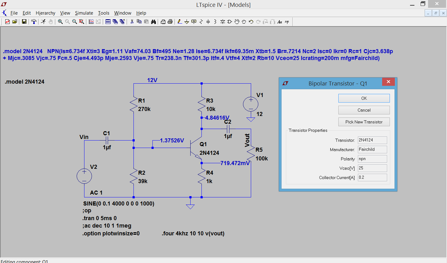
2. I have been reading the excellent tutorials from Mooly and particularily this post: https://www.diyaudio.com/community/...from-beginner-to-advanced.260627/post-4047521. I wanted to a add a model for a replacement transistor that I used before (a KSC1845). In the tutorial, it shows that when the model is used, the information is updated when right-clicking on the transistor. On my simulation, most of the info is empty. I'm doubting it is used. What I am doing wrong?

Nothing is critical here, this is just for personal learning but as always, I big thanks to anybody who can provide solutions or suggestions.
1. I have been trying to replicate the left preamp channel of my vintage receiver (a Sony STR-6045) and I am not successful at getting the voltages showed on the schematic. The preamp is called "Equalizer Amplifier Section" in the attached schematic. I'm attaching the ltspice file here.
In my LTSpice file, I have also added a 1Khz source of about 0.25 Volt RMS from the auxiliary jack.
2. I have been reading the excellent tutorials from Mooly and particularily this post: https://www.diyaudio.com/community/...from-beginner-to-advanced.260627/post-4047521. I wanted to a add a model for a replacement transistor that I used before (a KSC1845). In the tutorial, it shows that when the model is used, the information is updated when right-clicking on the transistor. On my simulation, most of the info is empty. I'm doubting it is used. What I am doing wrong?
Nothing is critical here, this is just for personal learning but as always, I big thanks to anybody who can provide solutions or suggestions.
Attachments
That info in the popup box is from the device model definitions in the library. It’s optional and only used as a selection guide as to what those device specs are if they are part of that models definition. If you have access to the library you can add that missing information yourself but it’s not necessary for the model to work
Thank you for your reply. But are you sure? In Mooly's example, the properties are displayed on the custom model.
https://www.diyaudio.com/archive/gallery/data/1966/Copy_and_Paste_4.PNG
https://www.diyaudio.com/archive/gallery/data/1966/Copy_and_Paste_4.PNG
For that device in the library the information is there so it’s used in the form window.
Take a look at the bjt library and find out for yourself how it gets defined. It’s an ASCII file
Take a look at the bjt library and find out for yourself how it gets defined. It’s an ASCII file
OK, I have to agree with you. Thank you for your answer. Now if someone could hint me for my first question, that would be wonderful!

Also, R509 feeds two channels, so to simulate one channel, change it to 2x=66k. The results are close but not exact. But then these voltages may be what you get when you measure them with an analog meter 20K/V * 50Vscale + 1Meg, 20K/V * 10Vscale = 200K, typical of the time.
Also, 400mV input overdrives even the AUX setting.

Also, 400mV input overdrives even the AUX setting.
Thanks a lot Steve. For the switches, I wasn't too sure but I had definitely missed the short at R510.
For the amplitude I chose 400mV because I had 0.25V RMS when testing with a signal generator (Vp=√2*Vrms=√2*0.25V=0.354V) during a recap. I read somewhere that line-level signals were from 0.316 Vrms to 1.5 Vrms. So I was even below this range. Did I miscalculated it or misconfigured it? Maybe I'm confusing the amplitude and the AC amplitude? Should it be different?

For the amplitude I chose 400mV because I had 0.25V RMS when testing with a signal generator (Vp=√2*Vrms=√2*0.25V=0.354V) during a recap. I read somewhere that line-level signals were from 0.316 Vrms to 1.5 Vrms. So I was even below this range. Did I miscalculated it or misconfigured it? Maybe I'm confusing the amplitude and the AC amplitude? Should it be different?
Last edited:
Amplitude is in Vrms and used for transient analysis.
AC amplitude is used for, as it says “AC” or freq/phase response analysis.
AC amplitude is used for, as it says “AC” or freq/phase response analysis.
Ok, thanks for the clarification rsavas. But Steveu is right, the signal is clipping in my simulation if I use SINE(0 0.3536 1000) AC 0.25. Not sure if it is a LTSpice issue because 0.25V seems right to me.
- Home
- Design & Build
- Software Tools
- Schematic to LTSPICE questions