Here is the next in the series:
http://www.diyaudio.com/forums/chip...ator-chip-amp-family-welcomes-new-member.html
It is a (relatively) efficient class A single ended stereo amplifier utilizing the correlation between L and R channels to improve efficiency.
This one is a really top-class amplifier, boasting less than one ppm THD!
Have fun!!!
Attachments
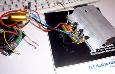
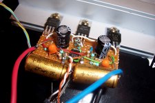
Here are pics of the prototype.
I haven't made any measurements yet.
But I used it as headphone amplifier, to check that the SE efficiency scheme had no negative impact on real audio signals.
I don't know whether I still have any bits of brain left inside my skull: the thing puts out 2.5W/ch. Sheer madness.
Anyway, the results look good: even when there is a strong stereo differentiation, there are no discernible negative effects, and the separation remains perfect.
Attachments

Here are some test results. Unfortunately, my poor old ST1700B didn't let me go very far or deep into the measurements.
At 1KHz, the THD indication was the same as the noise floor of the distortion-meter itself: 0.0012%.
The residue on the oscilloscope did show some second harmonic, buried in the noise of THD-meter, but it was insufficient to influence the reading on the meter.
I can safely say that the distortion (at full power, just before clipping) is <0.001%, and probably significantly lower (but probably not as low as in the sim).
The power bandwidth extends to ~30KHz. Beyond, the waveform breaks down, probably due to insufficient SR.
The small signal bandwidth (@2Vpp output) is 140KHz.
The opamp was a LF353.
All the measurements were made with both channels in service and loaded with 8R, and receiving an identical signal.
Impressive results from a LM317/337.
What about using this circuit for a bridge mode amplifier?
This would avoid possible performance decrease due to strong differentiation of stereo Signal.
To still achieve the efficiency advantage by correlation is all to do to replace the lm317 with lm337 for correlation?
1543
What about using this circuit for a bridge mode amplifier?
This would avoid possible performance decrease due to strong differentiation of stereo Signal.
To still achieve the efficiency advantage by correlation is all to do to replace the lm317 with lm337 for correlation?
1543
Why not, but you have to carefully evaluate what is to be gained by doing that.Impressive results from a LM317/337.
What about using this circuit for a bridge mode amplifier?
This would avoid possible performance decrease due to strong differentiation of stereo Signal.
In SE class A, the current source determines the peak output current.
With the 317's, that's what limits the output power on 8R (bias=800mA, ~half the max current of the 317).
By bridging, you could increase the output power, but on a load larger than 8R.
Not very convenient.
There is another path to use the correlation: instead of the middle 317 used as a current source with a relatively low voltage across thanks to correlation, you could adopt a complementary scheme:
The middle regulator would be modulated by the L+R signal, and one of the channels and outputs would have its polarity reversed.
I will probably try this scheme too, but it's a bit more complicated to implement.
Hi, Elvee,
I tried your schematics on LTSpice, but I didn't same result.
The L channel works, but the THD is worse.
The R channel doesn't work well.
I think it because I use the different models of LM317/LM337.
I use the following models,
LM317:
How to use LM317 LTspice Model
LM337:
http://www.edaboard.com/thread8834.html
Please show me your models.
I did have problems with the 317/337 models: the ones I found seem to apply to the M versions: the current limitation happens at ~500mA, the third of what it should be.
To overcome the limitation, the trick I used was to parallel two of them.
It is not visible in my schematics, because I overlaid exactly the two operators (this gives an error message at the beginning of the sim, but I just ignore it).
Here are the sub files and the schematic:
To overcome the limitation, the trick I used was to parallel two of them.
It is not visible in my schematics, because I overlaid exactly the two operators (this gives an error message at the beginning of the sim, but I just ignore it).
Here are the sub files and the schematic:
Attachments
Hi Elvee,
I tried your circuit on LTSpice, but it didn't work well.
The L channel works well, but the THD is worse than yours.
And it doesn't get sine wave from the R channel.
I think that my models of LT317/337 are different from yours, and it make the result.
I got models from following page:
http://www.diyaudio.com/forums/parts/5025-who-can-help-spice-models-lm317-lm337.html.
Could you tell me where you get your model?
The model that Elvee posted has a problem delivering current more than about 1/2 amp. It also didn't (for me at least) have an accurate ref voltage. I modded it slightly (after some googling) to get closer to the 1.25V ref voltage.
*LM317 TI voltage regulator - pin order: In, Adj, Out
*TI adjustable voltage regulator pkg:TO-3
.SUBCKT LM317D 1 2 3 **Changes my be required on this line**
J1 1 3 4 JN
Q2 5 5 6 QPL .1
Q3 5 8 9 QNL .2
Q4 8 5 7 QPL .1
Q5 81 8 3 QNL .2
Q6 3 81 10 QPL .2
Q7 12 81 13 QNL .2
Q8 10 5 11 QPL .2
Q9 14 12 10 QPL .2
Q10 16 5 17 QPL .2
Q11 16 14 15 QNL .2
Q12 3 20 16 QPL .2
Q13 1 19 20 QNL .2
Q14 19 5 18 QPL .2
Q15 3 21 19 QPL .2
Q16 21 22 16 QPL .2
Q17 21 3 24 QNL .2
Q18 22 22 16 QPL .2
Q19 22 3 241 QNL 2
Q20 3 25 16 QPL .2
Q21 25 26 3 QNL .2
Q22A 35 35 1 QPL 2
Q22B 16 35 1 QPL 2
Q23 35 16 30 QNL 2
Q24A 27 40 29 QNL .2
Q24B 27 40 28 QNL .2
Q25 1 31 41 QNL 5
Q26 1 41 32 QNL 50
D1 3 4 DZ
D2 33 1 DZ
D3 29 34 DZ
R1 1 6 310
R2 1 7 310
R3 1 11 190
R4 1 17 82
R5 1 18 5.6K
R6 4 8 100K
R7 8 81 130
R8 10 12 12.4K
R9 9 3 180
R10 13 3 4.1K
R11 14 3 5.8K
R12 15 3 72
R13 20 3 5.1K
R14 2 24 12K
R15 24 241 2.4K
R16 16 25 6.7K
R17 16 40 12K
R18 30 41 130
R19 16 31 370
R20 26 27 13K
R21 27 40 400
R22 3 41 160
R23 33 34 18K
R24 28 29 160
R25 28 32 3
R26 32 3 .1
C1 21 3 30PF
C2 21 2 30PF
C3 25 26 5PF
CBS1 5 3 2PF
CBS2 35 3 1PF
CBS3 22 3 1PF
.MODEL JN NJF(BETA=1E-4 VTO=-7)
.MODEL DZ D(BV=6.3)
.MODEL QNL NPN(EG=1.22 BF=80 RB=100 CCS=1.5PF TF=.3NS TR=6NS CJE=2PF
+ CJC=1PF VAF=100 IS=6E-13 NF=1.1623)
.MODEL QPL PNP(BF=40 RB=20 TF=.6NS TR=10NS CJE=1.5PF CJC=1PF VAF=50 IS=6E-13 NF=1.1623)
.ENDS LM317 **changes may be required on this line**
I've also got a non-discrete model which does not have the current limitation, but I think is not as realistic.
.SUBCKT LM317 IN ADJ OUT
*
* POSITIVE ADJUSTABLE VOLTAGE REGULATOR BEHAVIORAL MODEL
*
JADJ IN ADJ ADJ JADJMOD ;ADJUSTMENT PIN CURRENT
VREF 4 ADJ 1.250
DBK IN 13 DMOD
CBC 13 15 800.0E-12
RBC 15 5 1.000E3
QPASS 13 5 OUT QPASSMOD
RB1 7 6 1
RB2 6 5 128.3
DSC 6 11 DMOD
ESC 11 OUT VALUE={5.646-.6667*V(6,5)*V(13,5)}
DFB 6 12 DMOD
EFB 12 OUT VALUE={8.822-.4024*V(13,5)+5.250E-3*V(13,5)*V(13,5)
+ -.6667*V(13,5)*V(6,5)}
*
EB 7 OUT 8 OUT 6.939
RP 9 8 100
CPZ 10 OUT 3.183E-6
*
DPU 10 OUT DMOD ;POWER-UP CLAMPLING DIODE
RZ 8 10 .1
EP 9 OUT 4 OUT 100
RI OUT 4 100MEG
*
.MODEL QPASSMOD NPN (IS=30F BF=50 VAF=1.500 NF=1.701)
.MODEL JADJMOD NJF (BETA=50.00E-6 VTO=-1)
.MODEL DMOD D (IS=30F N=1.701)
.ENDS
Tony.
Hi Elvee,
I tried your circuit on LTSpice, but it didn't work well.
The L channel works well, but the THD is worse than yours.
And it doesn't get sine wave from the R channel.
I think that my models of LT317/337 are different from yours, and it make the result.
I got models from following page:
http://www.diyaudio.com/forums/parts/5025-who-can-help-spice-models-lm317-lm337.html.
Could you tell me where you get your model?
I posted my models in #12 above. Just remove the .txt to use them.
PS
And don't forget to parallel them (or use my .asc schematic, or Wintermute's fix)
I didn't look at this carefully last night. It's going to take some time to get my head around it! Could you give an explanation as to how the circuit actually works Elvee? It's a very novel approach to creating an amp!!
It is pretty simple in fact: on the schematic, just ignore the bottom regulator for the moment (suppose Out L is connected to the negative rail).
The upper regulator will act as a follower (common collector or drain): its Out will follow closely the Adj terminal, it will always be 1.25V higher.
The regulator can be seen as a depletion device having a very sharp transconductance.
The bottom regulator is wired as a current sink, and the combination of the two forms a classic single-ended follower, but having a much higher accuracy than what a discrete device could achieve: in a BJT for instance, the Vbe is modulated by the emitter current, and this causes non-linearities and a non-zero output impedance.
The follower made from the two regulator is almost perfect.
But on top of that, it is included in a loop with the opamp, whose role is to further improve the linearity, and provide voltage gain.
Now, here is the original stuff:
SE amplifiers are notoriously inefficient.
Here, the current source/sink is put in common between the two channels, and the voltage one needs to apply across it doesn't need to cover the full output swing of the outputs: since in a stereo system, the L and R signals are largely correlated, the two outputs will move in a synchronous manner, and that means the current source needs much less voltage headroom than if two completely separate amplifiers were constructed.
This means that the amplifier is not capable of providing its full output power when the two channels are completely uncorrelated, but this rarely happens, and the combination of the two situations is even rarer.
It does work in practice, I have listened to it extensively, on real audio signals, and I have never noticed any clipping, even when there was a strong stereo differentiation.
- Home
- Amplifiers
- Chip Amps
- SE class A regulator-chip-amp madness