All,
I've got my Mitsubishi DA-F20 tuner back from an alignment and refresh, and I'm building Brian Beezley's "Shorter Yagi for 88-92 MHz" because the only stations around here with any sound quality are in this range.
I will need to minimize multipath distortion. I've looked at Mr. Beezley's quadrature multipath monitor circuit on his website, but I can't afford another project in progress right now. We have an XY o'scope at work that I can borrow.
On the back of the tuner is a "multipath detector" jack labeled V and an "FM detector out" labeled H. How can I see multipath on the scope? I can't pick anything up on Google.
Last edited:
Connect FM detector to the X input, and multipath to the Y input. You will then see a trace which varies with programme content. The width depends on loudness. The top should be a smooth curve drooping a little at the left and right ends - this is essentially your IF filter response. If there are wiggles in this curve you have multipath.
FM Multipath O'scope Settings
DF96 and Everyone,
I have at last installed Brian Beezley's Tiny-Backlobe Narrowband Yagi, sized for a classical station at 89.7 MHz, in my attic. I've borrowed the work 'scope and connected the FM detector out to X and the "multipath" to Y on my DA-F20. Time is set at 5ms/div, vertical at 0.1 v/div, horizontal at 0.1 v/div, and this is what it looks like. It varies with the level of the audio, larger when louder.

I'd like it to look like this image from Brian's website, showing no multipath and multipath respectively on his scope.

Am I on the right track? Maybe I should dial in more volts per division on vertical to flatten out the dancing trace and make it flatter?
Thanks!
Paul
DF96 and Everyone,
I have at last installed Brian Beezley's Tiny-Backlobe Narrowband Yagi, sized for a classical station at 89.7 MHz, in my attic. I've borrowed the work 'scope and connected the FM detector out to X and the "multipath" to Y on my DA-F20. Time is set at 5ms/div, vertical at 0.1 v/div, horizontal at 0.1 v/div, and this is what it looks like. It varies with the level of the audio, larger when louder.
I'd like it to look like this image from Brian's website, showing no multipath and multipath respectively on his scope.
Am I on the right track? Maybe I should dial in more volts per division on vertical to flatten out the dancing trace and make it flatter?
Thanks!
Paul
External Not Time Base?
Okay, I tried connecting the X lead to the external BNC in the Trigger section and selected external as the source, but that just made a vertical line, so I put it back. That may not have been what you meant by selecting external in rather than the time base for the horizontal axis.
I was able to flatten the traces out by changing X to 20 mV/div and Y to 1.0 v/div. The traces pulse horizontally with volume. Here is the scope during a quiet passage:

When the orchestra or whatever is playing continuously there appears to be a slight rise on the right side of this noisy curve. Maybe I should go up and aim my antenna at the hills instead of the radio tower to make multipath worse. Then I could look at the scope to see if it has more bumps.
But from the picture, am I doing this right?
Thanks,
Paul
Okay, I tried connecting the X lead to the external BNC in the Trigger section and selected external as the source, but that just made a vertical line, so I put it back. That may not have been what you meant by selecting external in rather than the time base for the horizontal axis.
I was able to flatten the traces out by changing X to 20 mV/div and Y to 1.0 v/div. The traces pulse horizontally with volume. Here is the scope during a quiet passage:
When the orchestra or whatever is playing continuously there appears to be a slight rise on the right side of this noisy curve. Maybe I should go up and aim my antenna at the hills instead of the radio tower to make multipath worse. Then I could look at the scope to see if it has more bumps.
But from the picture, am I doing this right?
Thanks,
Paul
You need to view one against the other, the horizontal time base does not come into it all. Right now you are just viewing the audio and nothing else - no multipath indication.
I do not know the sensitivity of the x (horizontal) input on your scope but you may need gain or attenuation to get it to work properly.
Edit: Looking at your scope it does not appear that it can do it, you have an external trigger input, not an external input. You won't be able to display lissajous figures either.. http://en.wikipedia.org/wiki/Lissajous_curve
Scope Can't Show Multipath?
Okay, so if I send 1 kHz through a Y-cable, then only one lead through a capacitor and then to the Y scope input, and the other straight to the X scope input, I won't get some kind of oval shape?
Meanwhile back at the DA-F20 back panel, there are dedicated scope RCA jacks on the right:
Okay, so if I send 1 kHz through a Y-cable, then only one lead through a capacitor and then to the Y scope input, and the other straight to the X scope input, I won't get some kind of oval shape?
Meanwhile back at the DA-F20 back panel, there are dedicated scope RCA jacks on the right:
Attachments

He has X-Y capability - there is a button for it. The two channels are even labelled X and Y, as an alternative to 1 and 2.
The scope clearly has X-Y capacity as DFsays. there's even a separate button for it in the horisontal section.
However - if you look closely, Ch-1 is also marked X and Ch-2 is marked Y, amplifiers, attenuators and all......😉
and - there's also a XY switch setting in the 1/2 channel selector......
Reading or googling the user manual might be helpful......
However - if you look closely, Ch-1 is also marked X and Ch-2 is marked Y, amplifiers, attenuators and all......😉
and - there's also a XY switch setting in the 1/2 channel selector......
Reading or googling the user manual might be helpful......
Last edited:
Don't know how I missed the X-Y input markings and the setting on the switch, guess I was way too focused on the time base.. It's obvious, and set to X-Y mode should give a valid multipath indication.
Why did I not think of Googling the user manual? I think I will also go up to the attic and point the antenna in a bad direction to see what multipath looks like. I might have guessed the direction correctly when I first installed it.
Last edited:
The Plot Thickens with Loudness
Okay (or, Right, as the British would say)
Wife's out of the house, so I'm fiddling with my antenna. Went up to the attic and pointed the antenna away from the transmitter and towards Raleigh, NC, USA and its humble skyline.
Here are two views, the first with full orchestra and the second with almost silence:


Now this I think I can work with. "O" equals bad, flat line equals good. Good thing it's a classical station that has a lot of silence.
Right now maybe I could decrease the voltage per division in order to make a larger circle when it is quiet, not worry about the music going off the scale, and then rotate the antenna so that the trace is flat. This is going to be subtle.
Okay (or, Right, as the British would say)
Wife's out of the house, so I'm fiddling with my antenna. Went up to the attic and pointed the antenna away from the transmitter and towards Raleigh, NC, USA and its humble skyline.
Here are two views, the first with full orchestra and the second with almost silence:
Now this I think I can work with. "O" equals bad, flat line equals good. Good thing it's a classical station that has a lot of silence.
Right now maybe I could decrease the voltage per division in order to make a larger circle when it is quiet, not worry about the music going off the scale, and then rotate the antenna so that the trace is flat. This is going to be subtle.
O Lissajous
This time I decreased the voltage per division. First is wrong way, second is aimed at the transmitter. Both are during quiet passages or announcer pauses.


This time I decreased the voltage per division. First is wrong way, second is aimed at the transmitter. Both are during quiet passages or announcer pauses.
Fine Aiming
Oops, not to the left:

Hmm, the other way is not bad:

There are hills to the left and the antenna must be nulling more multipath if it misses to the right.
Oops, not to the left:
Hmm, the other way is not bad:
There are hills to the left and the antenna must be nulling more multipath if it misses to the right.
Here is a scan from the owners manaul, Marantz Model 20.
General overview. I never got to put up my outdoor antenna, but the folded dipole hung on the wall shows pretty much the same thing. Never got an "o" frm anything, but have had a fuzzy ball far different from the scramble of the audio display. Even found once, a station that did broadcast out of phase. A long time ago.
General overview. I never got to put up my outdoor antenna, but the folded dipole hung on the wall shows pretty much the same thing. Never got an "o" frm anything, but have had a fuzzy ball far different from the scramble of the audio display. Even found once, a station that did broadcast out of phase. A long time ago.
Attachments
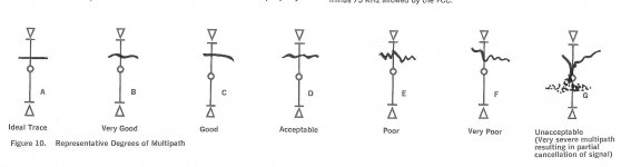
A Flat Grimace Means No Multipath
Hey gvasale,
Thanks for the Marantz manual Figure 10 - - I'm wondering if, when I aimed the attic antenna away from the radio station and at the low mountains to our west, the multipath was worse than Unacceptable and was so out of phase it traced a circle?
My scope is behaving more like the Audio button on the Marantz than the Multipath button. With sound content, it's scrambled, I can only read silent segments. Checked the attached video of a 2500 and the user presses the Multipath button at 0:16. He tunes from The Doors Riders on the Storm with very good multipath, to Billy Ocean with quite a bit:
marantz 2500 clip - YouTube
Maybe there is some extra filtration in those dedicated scopes. Do they only read the pilot signal and nothing else? One thing I haven't done is switch to Mono while testing.
Here's the basic question: What is the built-in o'scope doing differently with the Audio setting versus the Multipath setting, and how do we duplicate that on a general purpose scope?
I doubt you could ever get a circle, not with program material. I'm not enough of a technician to be able to answer if it is reading a pilot signal, but I think not. I'm guessing in the tuning mode its reading something after it IF...discriminator. Can you read a schematic? I've got the service manual, though I didn't refer to it in this case...I'll check to see of there's a block diagram. Be a while for the UTube on dialup.
Calling Tuner Techs!
Old school is good school! Take your time and enjoy the Marantz while that page loads.
Alright tuner technical guys: Marantz onboard scopes had three settings, Tuning, Audio and Multipath. What do they measure from the detector outputs, and how can we duplicate that with an oscilloscope?
Thanks!
PaulFX
There is a block diagram in the service manual. It appears the scope feed comes from the MPX matrix board. If you would like, I can scan the block diagram & post it here tomorrow. Funny, for the time I spent trying to learn radio & tv service in the early 70s they always called the circiut in which the carrier is taken from the program signal the detector for AM & discriminator for FM as I remember.
- Status
- Not open for further replies.
- Home
- Source & Line
- Analogue Source
- Seeing or Hearing FM Multipath