Hello,
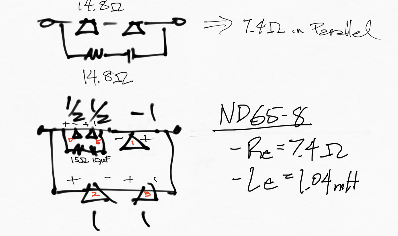
I want to wire up a 5-element line array of full range speakers with the following amplitudes [1/2, -1, 1, 1, 1/2].
Using Dayton ND65-8 drivers for this example: Re = 7.4Ω, Le = 1.04mH @1K
Is this correct? and do I need a Zobel Network for the 2x1/2 amplitude speakers?
I want to wire up a 5-element line array of full range speakers with the following amplitudes [1/2, -1, 1, 1, 1/2].
Using Dayton ND65-8 drivers for this example: Re = 7.4Ω, Le = 1.04mH @1K
Is this correct? and do I need a Zobel Network for the 2x1/2 amplitude speakers?

I see how you get [1,-⅔,⅔.⅔,1] from the diagram.
But how do I wire up [1/2, -1, 1, 1, 1/2]?
Also, is there an easy too to draw up these diagrams?
But how do I wire up [1/2, -1, 1, 1, 1/2]?
Also, is there an easy too to draw up these diagrams?
Looks like you're trying to get a Bessel array, see:
A Paul Kemble web page - speaker bessel arrays.

And:
https://www.pearl-hifi.com/06_Lit_Archive/15_Mfrs_Publications/Harman_Int'l/AES-Other_Publications/Effective_Performance_of_Bessel_Arrays.pdf
A Paul Kemble web page - speaker bessel arrays.
And:
https://www.pearl-hifi.com/06_Lit_Archive/15_Mfrs_Publications/Harman_Int'l/AES-Other_Publications/Effective_Performance_of_Bessel_Arrays.pdf
Attachments

Last edited:
That’s perfect. Generally speaking, what’s the trade off between choosing the series vs parallel configuration? Is the critical issue if the amp can drive a 2.8ohm load?
yes. 2.8ohm may damage your amp or cause elevated distortion from the amp. At 28ohm it may not go loud enough before the amp clips.
I actually like your original idea the best, as it has the potential to give a near 8ohm impedance. The resistor and capacitor should be a resistor and inductor instead. The resistor/inductor act as two series dummy drivers that have an impedance that looks like a driver but makes no sound. Therefore, they should equal the Re and Le of two drivers so R=14.8ohm and L=2.08mH.
It will not be perfect as the Re and Le T/S parameters are a simplified approximation. They do not take into account the mechanical resonance and the fact that the voice coil inductance is lossy, however I think the effects will be minor. The -1 driver will likely drive a little louder in the bass and treble than it should because of this. If you're keen you can experiment in software like Xsim and add more components to try to make the dummy circuit more closely approximate the real impedance.
Last edited: