I picked up a PPI pc2600.2 at the local pawn store for $10. The amp powers up, but I have ~2.7v of DC offset on the R channel.
Does anyone know where I can find a service manual?
Does anyone know where I can find a service manual?
Have you tried zeroing the DC with the offset pot?
What resistance do you read for A and B in the following applet:
http://www.bcae1.com/temp/ppidriverboardresistoroverlay01.swf
What resistance do you read for A and B in the following applet:
http://www.bcae1.com/temp/ppidriverboardresistoroverlay01.swf
Email subscriptions are not working for whatever reason....
Non of the pots are labeled on what they do. I have not found any documentation about the amp. Small rotations do nothing about the offset.
Where did that applet come from?
Ceramic driver card?
Non of the pots are labeled on what they do. I have not found any documentation about the amp. Small rotations do nothing about the offset.
Where did that applet come from?
Ceramic driver card?
The low value pots are bias. They won't work while you have the jumpers on the 2 pin headers. The high value pots are DC offset.
That applet is part of the tutorial I sell.
I've never seen 50 ohms and it's very odd that you get three 50 ohm and one 100 ohm. '
edit: Did you have additional resistors soldered on the board when you took the readings? If so, that's the reason you got those readings. The 100 ohm reading would indicate that the original resistor is open.
Don't solder anything on that board unless absolutely necessary.
Do you see any cracked solder joints on the driver board?
Last edited:
Resistors were soldered in.
The pad under the red B is not attached. I have not found any broken solder joints otherwise.
R side now reads Mohms on both A/B test points.
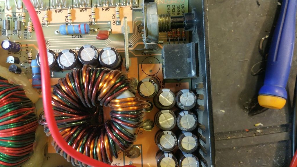
It looks like the amp was dropped at one time. The capacitor behind the Qbase connector is gone and the one next to it was at an odd angle.
The pad under the red B is not attached. I have not found any broken solder joints otherwise.
R side now reads Mohms on both A/B test points.
It looks like the amp was dropped at one time. The capacitor behind the Qbase connector is gone and the one next to it was at an odd angle.
Email subscriptions are not working for whatever reason....
Non of the pots are labeled on what they do. I have not found any documentation about the amp. Small rotations do nothing about the offset.
Where did that applet come from?
Ceramic driver card?
Yes,driver card mentioned by Perry...U can try swap the cards between channels,see how it goes if u are not sure the driver card problem or other thing else...
Last edited:
Re-check all transistors (even the small TO-92) in that channel. That resistor feeds the driver transistors on the ceramic board. It's likely that whatever the ceramic board is driving is shorted.
Did you notice if the amp drew excessive current when you powered it up?
Did you notice if the amp drew excessive current when you powered it up?
- Status
- Not open for further replies.
- Home
- General Interest
- Car Audio
- Service manual for PPI pc2600.2?