Shunt Regulators.
Power supply regulation is a high end method to come closer to an “ideal” power supply.
For a quick definition of Ideal, the power supply would be noise free, zero output impedance, and infinite line rejection from Zero to Light.
The ideal power supply could also source or sink infinite current, and have perfect voltage regulation.
If you find one, do let me know.
For background, a look at Nelson Pass white paper on Power Supplies located in Pass DIY would be in order.
https://www.passdiy.com/project/articles/power-supplies
Many of my ideas have been taken from this DIYAUDIO thread simplistic-salas-low-voltage-shunt-regulator.
http://www.diyaudio.com/forums/powe...listic-salas-low-voltage-shunt-regulator.html
There are 2 Basic types of regulators, Series and Shunt.
In a series regulator, the Active element is in series with the load.
In a shunt regulator, the active regulator is in parallel with the load.
Advantage of the series regulator is simplicity, and efficiency. Basically the series regulator only passes current when the load needs it.
This feature would be useful on class AB amplifiers who have peak current many times in excess of their static current.
Advantage of shunt regulator is that the shunt can sink current from the load and still stay in regulation.
It is also reputed to “sound better”.
I want to go through a few of the basic shunt regulators and discuss options, enhancements and tradeoffs.
Basic Shunt Regulator
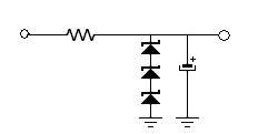
Here is our starting point, two parts that make a simple shunt regulator.
The 2 elements are a zener diode that conducts when the voltage rises above its breakdown voltage, and a resistor to limit the current when the zener conducts.
This makes for a simple, elegant, easily understood regulator.
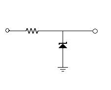
Simple, no feedback, what’s not to like?
The Equations you need to know are Ir = (Vin-Vout)/Rs
Or in English, the current through the resistor is the difference between the regulated voltage and the unregulated voltage, devided by the series resistance.
And the Vout is the value of the Zener diode. Ir = Iload + Iz . Restated: the current through the resistor is the current through the load plus the current through the zener.
Well, if we could find a perfect zener diode, it would work very well.
The larger the resistor is, the better the voltage divider is and the better it rejects noise from the raw power supply.
However, as the resistor value is increased, the larger the voltage needs to be in the unregulated supply and the more power is dissipated in the resistor.
We are going to take the concept and make it more real world.
Here is a more practical circuit shown with bypass the zener diode to lower noise of the zener.
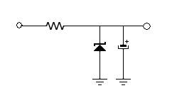
Real zener diodes are quietest at about 6 volts.
So for an 18V supply, use 3 in series rather than one 18V.
AC resistance of each of these is about 4 ohms, for a total of 12 ohms at AC.

Adding a transistor will lower the output resistance.
This takes the output Z down by a factor of the beta, or gain of the transistor.
So from 12 ohms, this is perhaps 2/10ohm. Not bad for 3 more parts.

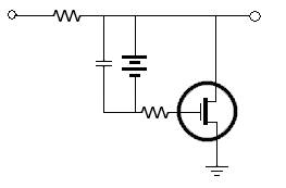
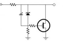
We could do the same thing with a FET and draw a more constant current through the zener string because the FET does not draw current like the NPN transistor did.
Since the FET needs 4 volts Gate to source to turn on, in our 18 V example, the Zener or battery is 14V to get an 18 V output.
A battery works because the only path to drain it is through the film capacitor or the FET gate, Batteries are noisy at higher current draw, but this one is just coasting.
or

For the 7’th installment, lets see if we can make out voltage reference better.
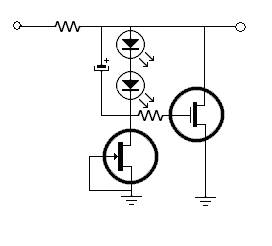
How about Using LED instead of the zener, which are quieter and more colorful.
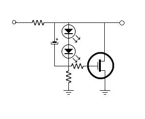
We can make even the LEDs better by replacing the resistor with a jfet wired as a CCS.
I am only showing 2 LED, 7 Red LED or 5 Blue LED might be required for the 14V reference needed for an 18V supply
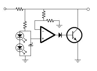
I favor discrete regulators rather than op amp based regulators, but this is a simple one that would be worth a try.
More feedback gives a lower output Z. However, specs may not be everything.

This is the bipolar equivalent. The diode is there to allow the op amp to use the raw supply.
Real op-amps can’t swing that close to the rail.
If there were plus and minus supplies, the diode would not be necessary.
Please continue in part 2
http://www.diyaudio.com/wiki/Shunt Regulation Part 2
Power supply regulation is a high end method to come closer to an “ideal” power supply.
For a quick definition of Ideal, the power supply would be noise free, zero output impedance, and infinite line rejection from Zero to Light.
The ideal power supply could also source or sink infinite current, and have perfect voltage regulation.
If you find one, do let me know.
For background, a look at Nelson Pass white paper on Power Supplies located in Pass DIY would be in order.
https://www.passdiy.com/project/articles/power-supplies
Many of my ideas have been taken from this DIYAUDIO thread simplistic-salas-low-voltage-shunt-regulator.
http://www.diyaudio.com/forums/powe...listic-salas-low-voltage-shunt-regulator.html
There are 2 Basic types of regulators, Series and Shunt.
In a series regulator, the Active element is in series with the load.
In a shunt regulator, the active regulator is in parallel with the load.
Advantage of the series regulator is simplicity, and efficiency. Basically the series regulator only passes current when the load needs it.
This feature would be useful on class AB amplifiers who have peak current many times in excess of their static current.
Advantage of shunt regulator is that the shunt can sink current from the load and still stay in regulation.
It is also reputed to “sound better”.
I want to go through a few of the basic shunt regulators and discuss options, enhancements and tradeoffs.
Basic Shunt Regulator
Here is our starting point, two parts that make a simple shunt regulator.
The 2 elements are a zener diode that conducts when the voltage rises above its breakdown voltage, and a resistor to limit the current when the zener conducts.
This makes for a simple, elegant, easily understood regulator.
Simple, no feedback, what’s not to like?
The Equations you need to know are Ir = (Vin-Vout)/Rs
Or in English, the current through the resistor is the difference between the regulated voltage and the unregulated voltage, devided by the series resistance.
And the Vout is the value of the Zener diode. Ir = Iload + Iz . Restated: the current through the resistor is the current through the load plus the current through the zener.
Well, if we could find a perfect zener diode, it would work very well.
The larger the resistor is, the better the voltage divider is and the better it rejects noise from the raw power supply.
However, as the resistor value is increased, the larger the voltage needs to be in the unregulated supply and the more power is dissipated in the resistor.
We are going to take the concept and make it more real world.
Here is a more practical circuit shown with bypass the zener diode to lower noise of the zener.
Real zener diodes are quietest at about 6 volts.
So for an 18V supply, use 3 in series rather than one 18V.
AC resistance of each of these is about 4 ohms, for a total of 12 ohms at AC.
Adding a transistor will lower the output resistance.
This takes the output Z down by a factor of the beta, or gain of the transistor.
So from 12 ohms, this is perhaps 2/10ohm. Not bad for 3 more parts.
We could do the same thing with a FET and draw a more constant current through the zener string because the FET does not draw current like the NPN transistor did.
Since the FET needs 4 volts Gate to source to turn on, in our 18 V example, the Zener or battery is 14V to get an 18 V output.
A battery works because the only path to drain it is through the film capacitor or the FET gate, Batteries are noisy at higher current draw, but this one is just coasting.
or
For the 7’th installment, lets see if we can make out voltage reference better.
How about Using LED instead of the zener, which are quieter and more colorful.
We can make even the LEDs better by replacing the resistor with a jfet wired as a CCS.
I am only showing 2 LED, 7 Red LED or 5 Blue LED might be required for the 14V reference needed for an 18V supply
I favor discrete regulators rather than op amp based regulators, but this is a simple one that would be worth a try.
More feedback gives a lower output Z. However, specs may not be everything.
This is the bipolar equivalent. The diode is there to allow the op amp to use the raw supply.
Real op-amps can’t swing that close to the rail.
If there were plus and minus supplies, the diode would not be necessary.
Please continue in part 2
http://www.diyaudio.com/wiki/Shunt Regulation Part 2
Attachments
-
 ShuntReg002.jpg2 KB · Views: 5,165
 -
 ShuntReg004.jpg2.3 KB · Views: 4,860
 -
 ShuntReg006.jpg2.6 KB · Views: 4,837
 -
 ShuntReg008.jpg4.4 KB · Views: 4,855
 -
 ShuntReg010.jpg3.9 KB · Views: 4,862
 -
 ShuntReg012.jpg4.4 KB · Views: 4,207
 -
 ShuntReg014.jpg5.7 KB · Views: 4,199
 -
 ShuntReg016.jpg6.7 KB · Views: 5,582
 -
 ShuntReg018.jpg8 KB · Views: 4,204
 -
 ShuntReg020.jpg8.1 KB · Views: 4,245
Last edited: