In this thread I'm documenting my development of an active filter for a 2-way design.
Purpose:
High-pass & low-pass filters at around 500Hz, for a 10" woofer + 3.5" wide-range.
The filters will be 2nd order (Sallen Key, unity gain), and that can modified by adding more stages.
By modifying component values it should be pretty easy to reconfigure for different cut-off frequencies and different Q, and the same basic layout can be used for high-pass, low-pass and notch versions.
Additionally, I wanted to challenge myself by using discrete buffers instead of op-amps. An earlier attempt was only marginally successful: single BC850x based buffers were usable at low volume but had too much IMD. In the latest version, I've been able to significantly reduce THD, and IMD should also be much lower as well. It is also far less dependent on volume. As long as component values for filtering are within reason, it doesn't even have to be push-pull, which simplifies things a lot.
Even at ~0.0005%THD, I still haven't been able to match a NE5534 version that I simulated for comparison. However, noise performance is about 6dB better.
By using N and P MOSFETs configured as Sziklai pairs, simulated THD measures around 0.000x% @ 1V at a few different frequencies from 100Hz to 2kHz that I've tested, for both HP and LP versions.
The circuit is not optimised yet, and doesn't include any pre-amp section or volume control. The previous prototype used a dual-gang pot for volume, but ultimately I'd prefer a switched resistor topology. The order of the stages: gain, filtering, volume, is TBD.
I'll have to measure the speakers again to see if they need anything different like a Linkwitz Transform, shelving filters or notches.
Filter Q:
I'm keeping the slopes gradual at the moment, avoiding excessive overshoot and ringing. I suppose that even if it's hard to see on a linear scale, logarithmic ears may be sensitive to it.
Overlap and gain and phase at XO point:
TBD.
I've manually played around with the exact slopes to get something "looks" right on a virtual oscilloscope, but I'm not sure what the combined response will look like in the real world just yet. The speakers are in separate boxes so the geometry is not fixed. This is another reason why I'm careful to avoid ringing: there is no guarantee that it will cancel out, so each speaker has to have smooth output, independent of any 'corrections' from the other speaker.
Total output noise is about 500nV @ 20kHz for the low pass version, and 800nV @ 20kHz for the high pass. However, that is likely to get swamped by power supply noise for the version shown.
Attachments


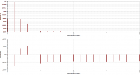

I may have spoken too soon about the source follower not 'matching' an NE5534 -- the op-amp is miles better at a 1V input signal. But at 3V the distortion products have skyrocketed, producing a flat harmonic series around 150uV.
It almost looks like some kind of clipping. There seems to be a certain threshold where a small change in signal amplitude produces a disproportionately huge jump in higher harmonics.
3V might be a bit high for my needs, except maybe for extreme peaks, but I'm keeping in mind for the volume control. (Should I attenuate ahead of the filters, for lower distortion but higher noise, or the other way around? Or may have two volume controls...? )
I've started looking at a J113 cascode. The perfectly matched devices in the simulation have strong cancellation of even harmonics. Detuning the resistor values brings them back. At 3V it's in 2nd place.
Attachments


Why not use current sources for biasing? The resistors you use now (R22, R40, R5, R30) will reduce loop gain, among other things.
Total output noise is about 500nV @ 20kHz for the low pass version, and 800nV @ 20kHz for the high pass. However, that is likely to get swamped by power supply noise for the version shown.
500nV in 20kHz bandwidth corresponds to about 3.5nV/rtHz in noise density which is pretty impressive for a MOSFET. Did you measure the 500nV or sim it?
Given R27, the 1k input resistor, contributes a minimum of 4nV/√Hz, and there are other larger values in the filter part of the circuit this clearly this is completely bogus! Perhaps 500nV/√Hz though? Ie 70µV rms500nV in 20kHz bandwidth corresponds to about 3.5nV/rtHz in noise density which is pretty impressive for a MOSFET. Did you measure the 500nV or sim it?
The fn of the low pass filter is 935.56 Hz, so 500 nV would correspond to roughly 16.35 nV/√Hz if all noise sources were in front of the filter stage (neglecting the difference between noise bandwidth and fn). The last voltage follower is not, though, so the noise level is still surprisingly low.
16.35 nV/√Hz corresponds to 16127 ohm at 300.15 K, which is close to the sum of the resistances of the input resistor and the filter resistors. I would expect a noise level of this order if the voltage followers were completely noiseless.
16.35 nV/√Hz corresponds to 16127 ohm at 300.15 K, which is close to the sum of the resistances of the input resistor and the filter resistors. I would expect a noise level of this order if the voltage followers were completely noiseless.
Last edited:

Just a few overall comments on your project I hope will help:
How are you dealing with offset and phase matching? Or @ 500 Hz, do you consider that not a problem?
If you are using different amplifiers, how are you dealing with different gain? Gain, not level.
Even for a "wide range" you probably want to have a really big cap in series with it. Don't forget the phase. A blocking cap well below your crossover probably means a big electrolytic. Just be aware.
And for a "wide range" you have a heck of a job to deal with eq. and other issues trying to push a driver out of the 10X rule-of-thumb. Been there, failed several times. Always had to add a tweeter and then deal with the uneven response through the midrange.
Modern op amps have all the features you are looking for in discrete and more. Well, no bragging rights, but they are very good. The music you are playing already whet through probably 100's of them. ( and a lot may be 5558's) Many tricks including biasing into class A ( see old POOGE articles) But any decent cap does need to be external from the op-amp which you can do discrete.
Be careful with simulations. I can adjust Spice parameters to give any distortion you want. At best they can be consistent and may perform only 10 times worse than the model, All you really need if you understand it.
Look carefully at how "perfectly" matched parts are. Usually way better than hand matching as they are thermally linked, but not always the equal of an op-amp internally.
Be careful trying to EQ bass up. Way too easy to get excessive distortion. Might I suggest a low Q sealed alignment. Blends with the room far better for real at listening response, not some modeled or nearfield "flat" which is terrible in a real room. A 10" with a Q of .5 and an F3 around 50 will give actual real deep bass. Not HT specials effects, but real music deep bass. Even F3 of 60.
Looking at these pop by the last couple of days, I keep thinking that a couple of simple things need to always be looked at.
1) Given you always listen along the plane that lies between the two point sources (drivers) of a two way, which is the optimal point that most of the time never happens, if you have any low pass transfer function L(S), then the high pass must be H(S) = UNITY - L(S). Doing this, driver issues aside, the output is flat. For a first order where L(S) is 1/(1+kS), this makes the high pass H(S) = 1 - 1/(1+kS) = kS/(1+kS). Do the math for higher orders, you get a pair of filters which are not necessarily the same dominant order to still satisfy being flat together. Be careful with this, making the low and high pass both of significant order (even second) means it probably isn't summing to unity, and thus has error in the crossover band.
2) Fixing the forced listening plane: at 500hz, you have two point sources whose wavelengths are short enough and produce the standard diffraction pattern. Never any good, and smack in the middle of much of your music content. You have two choices: a) make the shared wavelengths ridiculously long avoids that.... but you'll need a crossover point significantly lower (as in easily below 100), or, b) make the shared range of frequencies very very narrow. The choice of (b) is harder to do with analog components, the choice of (a) is easier. If you combine that with the excellent suggestion by tvrgeek in message#8 about a good sealed cabinet, etc, and you'll have a more coherent sounding speaker. That makes compensating low freq rolloff easier too, should you need it due to cabinet size considerations, etc.
Your mileage may vary. I do, however, find this always is a balancing act. Since the early 90's, i've taken to doing it all digitally (early adopter of dsp56k and cirrus logic components). Makes it easier, but, the basic dual point source problem never goes away.... you need to force it to be not so significant.
Various options are on the table, such as a JFET cascode. A low part count is not critical, but 2 FETs per gain stage seems very reasonable. A boosted op-amp might be another idea. I'm guessing a heavy capacitive load may be what's limiting op-amp performance.Why not use current sources for biasing? The resistors you use now (R22, R40, R5, R30) will reduce loop gain, among other things.
Physically separate boxes. I may build an adjustable speaker mount. Even if phases are aligned, it's only in one plane (preferably ear height) and I don't want off-axis or reflected sound to be compromised.Just a few overall comments on your project I hope will help:
How are you dealing with offset and phase matching? Or @ 500 Hz, do you consider that not a problem?
Long-term plan include custom amplifiers for the speakers as well. So the high-pass might get an output capacitor. The filters already have a 3rd pole because of DC decoupling, so I've tried to size those appropriately so they're 'somewhat' out-of-band.If you are using different amplifiers, how are you dealing with different gain? Gain, not level.
Even for a "wide range" you probably want to have a really big cap in series with it. Don't forget the phase. A blocking cap well below your crossover probably means a big electrolytic. Just be aware.
Tweeters are a can of worms I haven't touched yet. I kind-of want to avoid horn tweeters that go down to 500Hz, although I'm open to making a very shallow wave-guide. Especially one that curves back around the enclosure.And for a "wide range" you have a heck of a job to deal with eq. and other issues trying to push a driver out of the 10X rule-of-thumb. Been there, failed several times. Always had to add a tweeter and then deal with the uneven response through the midrange.
Given that the speakers are already far apart, I'm tempted to look for sweet spots around 1/2 or 1 wavelength of separation. Tuning for approx 0dB summing in the horizontal plane, and aiming for mild peaks / nulls off-axis (I'm not sure which would be more benign). Probably something in between an LR-2 and Bessel. I have a pair of 40L cubes (I know) with 10" woofers are sitting on the floor, and 3.5"'s in 4L boxes are on a table.Looking at these pop by the last couple of days, I keep thinking that a couple of simple things need to always be looked at.
1) Given you always listen along the plane that lies between the two point sources (drivers) of a two way, which is the optimal point that most of the time never happens, if you have any low pass transfer function L(S), then the high pass must be H(S) = UNITY - L(S). Doing this, driver issues aside, the output is flat. For a first order where L(S) is 1/(1+kS), this makes the high pass H(S) = 1 - 1/(1+kS) = kS/(1+kS). Do the math for higher orders, you get a pair of filters which are not necessarily the same dominant order to still satisfy being flat together. Be careful with this, making the low and high pass both of significant order (even second) means it probably isn't summing to unity, and thus has error in the crossover band.
2) Fixing the forced listening plane: at 500hz, you have two point sources whose wavelengths are short enough and produce the standard diffraction pattern. Never any good, and smack in the middle of much of your music content. You have two choices: a) make the shared wavelengths ridiculously long avoids that.... but you'll need a crossover point significantly lower (as in easily below 100), or, b) make the shared range of frequencies very very narrow. The choice of (b) is harder to do with analog components, the choice of (a) is easier. If you combine that with the excellent suggestion by tvrgeek in message#8 about a good sealed cabinet, etc, and you'll have a more coherent sounding speaker. That makes compensating low freq rolloff easier too, should you need it due to cabinet size considerations, etc.
Your mileage may vary. I do, however, find this always is a balancing act. Since the early 90's, i've taken to doing it all digitally (early adopter of dsp56k and cirrus logic components). Makes it easier, but, the basic dual point source problem never goes away.... you need to force it to be not so significant.
I may also add an all-pass filter for additional experimentation, and that will probably require a proper gain stage instead of a buffer.
- Home
- Source & Line
- Analog Line Level
- Simple active filter design for 2-way