I wanted two HUF76639P Mosfets for an amplifier and found an established UK company which specialises in supplying obsolete components. They had listed Fairchild HUF76639P and after they reassured me via email they were genuine, I ordered two.
I gathered from diyaudio that a type of curve tracer is the way to go for testing, so I tested them and compared them against two original Fairchild HUF76639P.
I modified a standard component IV curve tracer (#49: Simple Component Tester using Oscilloscope - Octopus Curve Tracer - YouTube) and played around in LTSpice to get something for Mosfets. Circuit as attached. It seemed to work OK and is pretty straightforward, but should there be a film capacitor somewhere?
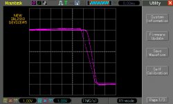
I initially had the 5V polarity reversed (yes, the arrow in the Mosfet symbol indicates the opposite direction to a transistor symbol arrow! 🙄) and it all took me a while, but here are the results, each screenshot is annotated. (x-axis is voltage applied to gate/source where 1 square = 1V, centre line is 0V, y-axis represents current through source/drain. Max current is seen at most negative voltage.)
Compared to two original Fairchild HUF76639P, the new Mosfets require rather more gate voltage before they respond, are not fully "on" at 3V and there is more variation between them than I would expect from genuine Fairchild devices. Fair comment? (They also look like recently manufactured devices.)
Although rather higher gate capacitance, the IRL2910 is a suggested modern replacement for the HUF and it looks like they have pretty similar response curves.
Notes:
Thanks in advance for any helpful feedback...
I gathered from diyaudio that a type of curve tracer is the way to go for testing, so I tested them and compared them against two original Fairchild HUF76639P.
I modified a standard component IV curve tracer (#49: Simple Component Tester using Oscilloscope - Octopus Curve Tracer - YouTube) and played around in LTSpice to get something for Mosfets. Circuit as attached. It seemed to work OK and is pretty straightforward, but should there be a film capacitor somewhere?
I initially had the 5V polarity reversed (yes, the arrow in the Mosfet symbol indicates the opposite direction to a transistor symbol arrow! 🙄) and it all took me a while, but here are the results, each screenshot is annotated. (x-axis is voltage applied to gate/source where 1 square = 1V, centre line is 0V, y-axis represents current through source/drain. Max current is seen at most negative voltage.)
Compared to two original Fairchild HUF76639P, the new Mosfets require rather more gate voltage before they respond, are not fully "on" at 3V and there is more variation between them than I would expect from genuine Fairchild devices. Fair comment? (They also look like recently manufactured devices.)
Although rather higher gate capacitance, the IRL2910 is a suggested modern replacement for the HUF and it looks like they have pretty similar response curves.
Notes:
I've got an AC transformer which gives 26V peak and the resistor divider R1 and R2 merely produces about 5v peak AC which gets applied to the Gate.
I used a 1K for R3 instead of 33R for the screenshots and the curve differences look comparable. (33R gives 150mA peak, 1K gives 5mA.)
The DSO was used in XY mode (X,Y probe locations marked on circuit). As Y measures voltage drop across resistor R3 it represents the current flow through it.
Sample LTSpice screenshot included for a random mosfet. After clicking on Y to get a voltage plot, right-click on x-axis time scale and replace "time" with "V(x)".
Thanks in advance for any helpful feedback...
Attachments
-
 HUFNEW1.bmp.jpg95.8 KB · Views: 201
 -
 HUFNEW2.bmp.jpg95.8 KB · Views: 202
 -
 HUFOriginal1.bmp.jpg96.8 KB · Views: 195
 -
 HUFORIGINAL2.bmp.jpg96.1 KB · Views: 190
 -
 IRL2910-5.bmp.jpg94.8 KB · Views: 191
 -
 IRL2910-9.bmp.jpg93.8 KB · Views: 88
 -
Mosfet IV tracer.asc1,006 bytes · Views: 74
-
 Mosfet IV tracer.png11.2 KB · Views: 92
Last edited:
I think I have the answer: by carefully measuring distances on the response curve images, the two new devices are matched to within 0.168V (which is reasonable) BUT the new HUF need 1.19V more for the same output compared to genuine Fairchild devices. I'm pretty sure that isn't within spec (especially for logic level mosfets) and therefore the new devices are not genuine Fairchild devices...