I have been trying to simulate Transitional Miller Compensation (TMC) to see what kind of benefits it might provide before employing it in a circuit. In one circuit, there is only a single Miller capacitor C9=150 pF (C3=0 pF). In the TMC circuit, there are two capacitors and a resistor in the compensation loop: R107=470 ohms, C9=68 pF, C13=470 pF. I have tried all kind of combinations of R107, C9, and C13, and the distortion does not seem to be significantly different at all. In both cases, the distortion seems to be on the order of 0.005% to 0.01%. Practially speaking, there is a peak in the gain around 1 MHz that seems to need to be suppressed in practice to prevent oscillation by setting C3=100 pF so that the distortion increases to 0.02% to 0.03%.
I am performing the simulation at 20 kHz with full power input (equivalent of about 200 W at 8 ohms) and using Fourier analysis to find the magnitude of the harmonics of the 20 kHz primary frequency.
Has anyone simulated this before and been able to get very low distortion? Is there a limitation just due to the crossover distortion anyways, or is there a better way to simulate it? Perhaps I am just running into limitations of open loop bandwidth?
Attachments


we don't see any info on other component values, characteristics of semi's used, operating points, etc. so a bit of a stab in the dark.
having said that, a miller cap value of 150pF seems rather large, perhaps swamping some other issues that need to be flushed out first? what info did you use to select initial values for all the compensation resistors and capacitors?
if you just want to see the effects of TMC versus regular Miller compensation, maybe try a much simpler circuit first so you have less variables to juggle?
maybe even use ideal components and only change the compensation scheme ...
@Profdc9
There are several possible reasons why you see no benefit
When supplying the .asc file I could give it a try and return my findings to you.
Hans
There are several possible reasons why you see no benefit
When supplying the .asc file I could give it a try and return my findings to you.
Hans
Maybe this
Ovation e-Amp: A 180 Watt Class AB VFA Featuring Ultra Low Distortion
can give you idea. The TMC is beneficial if your open loop is far less than 20khz. Then, the output to VAS feedback reduces the distortion of the output stage at audio frequencies.
Ovation e-Amp: A 180 Watt Class AB VFA Featuring Ultra Low Distortion
can give you idea. The TMC is beneficial if your open loop is far less than 20khz. Then, the output to VAS feedback reduces the distortion of the output stage at audio frequencies.
I have attached both ngspice files including the models. Hopefully you can use these with your flavor of spice.
Dan
Dan
@Profdc9
There are several possible reasons why you see no benefit
When supplying the .asc file I could give it a try and return my findings to you.
Hans
Attachments
I am using MJE15023/MJE15033 as shown and MJL3281/1302 as the power stage transistors. All others are 2N5551/2N5401s. I am using SPICE models for all of these. I have tried a smaller Miller cap and have not seen any significant difference in the distortion performance, only more of a tendency toward instability and oscillation.
I am starting from the C300 amplifier design and I was curious as to whether two pole feedback or TMC could improve on global feedback. Perhaps a really fast VAS transistor is needed to realize the benefit of TMC like a 2SA1381? Or perhaps putting a Darlington in the feedback loop is a bad idea. Not sure.
I am starting from the C300 amplifier design and I was curious as to whether two pole feedback or TMC could improve on global feedback. Perhaps a really fast VAS transistor is needed to realize the benefit of TMC like a 2SA1381? Or perhaps putting a Darlington in the feedback loop is a bad idea. Not sure.
we don't see any info on other component values, characteristics of semi's used, operating points, etc. so a bit of a stab in the dark.
having said that, a miller cap value of 150pF seems rather large, perhaps swamping some other issues that need to be flushed out first? what info did you use to select initial values for all the compensation resistors and capacitors?
if you just want to see the effects of TMC versus regular Miller compensation, maybe try a much simpler circuit first so you have less variables to juggle?
maybe even use ideal components and only change the compensation scheme ...
I simulated and then built it for my MOSFET amp. What it does is a difference in the distortion with frequency. Standard "safe" VAS loading distortion is higher, but decreases with frequency. 2-pole Miller is lower, but remains about constant. Where this shows up is at high frequency, typically above 20K, TMC is actually higher. So if you have cheap tweeters with nasty breakup, the HD may excite the tweeter breakup resulting in IM down in the audible range.
It took a couple of years experimenting with this. Most thanks to John Curl who pointed me in that direction. So if a cheap speaker, use VAS loading. If good speaker, TM was like a veil lifted. It will show up in LTSpice.
Bottom line, a Rotel 800 series sounded better on Paradigm Studio 20's, but when I built my Seas based mains, the HCA1500 and 2200 blew it's doors off, where they were darn right nasty on the Paradigms.
FWIW, I do not suggest trying to duplicate TM on a MOSFET amp. Stability margins are too tight. Took a few sets of outputs to match simulation with reality. It was worth it though. Self and Cordell both discuss this.
The title doesn't say about two pole, if you intend to consider, the two pole can give the same OLG as 1khz but with 20khz OLGB.
Comparison Of 2 Pole Compensations
Comparison Of 2 Pole Compensations
My version of 2 pole correction
Attachments

Last edited:
I have attached both ngspice files including the models. Hopefully you can use these with your flavor of spice.
Dan
Hi Dan,
Sorry but I can't import your netlist files into LTSpice, there are too many dissimilarities.
But I agree with Hayk that TPC is the way too go and not TMC.
Divide 150pF C9 into two caps having twice the size of C9 alone, and put a resistor in between them, your R107, the other side to gnd and not to the LS output.
Hans
What models are you using for the MJE15032/3 and MJL3281A/1302A?
ON Semi's prepared by Modpex leave a little, shall we say, to be desired.
If you are using those try looking for Bob Cordell's or Andy_C's models which are likely to be rather better.
ON Semi's prepared by Modpex leave a little, shall we say, to be desired.
If you are using those try looking for Bob Cordell's or Andy_C's models which are likely to be rather better.

The title doesn't say about two pole, if you intend to consider, the two pole can give the same OLG as 1khz but with 20khz OLGB.
Comparison Of 2 Pole Compensations
correction: 6khz not 1khz.
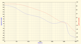
Looking at your Bode plot, it looks like the phase margin is really small, less than 20 degrees, from 30 kHz-1 MHz. Is this something to worry about?
My version of 2 pole correction
I am curious to know what simulation are used to adjust compensation.
When there is mention of phase margin, is that about open loop gain ?
How do you get open loop bode plots ?
As far as I know, the basic .ac simulations give close loop bode plots.
Is there a tool for that in ngspice ? or other simulators ?
With LTSpice I use a Tian probe, may be I am missing something, and a similar tool already exists.
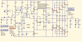
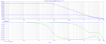
So I simulated the MC12 mods suggested. The schematic shows the modded circuit, the simulation, and the open loop gain. The amplifier is unstable and it oscillates.
I also tried two-pole compensation (TPC). It is stable but seems to provide little advantage over the conventional Miller approach.
Finally, I tried what Bob Cordell called Bridged T Compenation (BTC). This adds a small capacitor (I used 5 pF) across the TPC "T" network. It transitions somewhat more between a conventional Miller and a TPC approach. Again, the result is similar to TPC and not significantly different than the conventional Miller approach.
I usually have used the conventional 180 degrees phase margin/gain margin criteria to evaluate stability, but perhaps that does not apply here? In lieu of that, I have used transient response simulation to see if oscillation actually occurs. Also, to also test stability under different loads, I add more capacitance to the output as a more practical test. Definitely TPC and BTC seem less tolerant of added capacitance (with 0 uF output inductor), oscillating with as little at 10 nF added capacitance, than the conventional Miller approach, which can tolerate 30 or 40 nF. Since I would like the amplifier to be somewhat resilient to different loads (high capacitance cables, etc.), I think this is not a bad approach to testing what could cause oscillation in real-world environments.
Perhaps this amplifier design has some other place where distortion is introduced? For example, it uses a unipolar input and VAS. Maybe a symmetric input and VAS would be better?
Attachments
-
 TPC-openloop.png95.5 KB · Views: 125
 -
 TPC-simulation.png81.3 KB · Views: 179
 -
 TPC-schematic.png77.8 KB · Views: 222
 -
 MC12-openloop.png106.9 KB · Views: 212
 -
 MC12-simulation.png90.5 KB · Views: 205
 -
 MC12-schematic.png86.1 KB · Views: 220
 -
 BTC-schematic.png77.9 KB · Views: 163
 -
 BTC-simulation.png81.4 KB · Views: 139
 -
 BTC-openloop.png97.8 KB · Views: 130
You measured a much extended OLG in frequency, but no improvement in distortion with the TPC topology.
That’s very strange.
So I think you haven’t measured THD the proper way, with the right accuracy, the right time window length, enough settling time or whatever.
Hans
That’s very strange.
So I think you haven’t measured THD the proper way, with the right accuracy, the right time window length, enough settling time or whatever.
Hans
- Home
- Amplifiers
- Solid State
- Simulating single pole vs. Transistional Miller Compensation (TMC)