Hi all 🙂
I'm in the process of making a relay-based input selector. I've done a bunch of reading on how to minimise the impact relays have on the audio signal in the case of a power supply that's shared with the analog circuitry. I know the ideal situation would be a completely separate and isolated power supply for the coil (i.e. its own transformer, rectifier, etc) but this isn't always practical on a tight budget.
So, how to best implement this? A flyback diode is mandatory, but how useful is an additional RC snubber across the relay coil? I'm thinking a 47ohm resistor in series with a 100nF cap, with the two of them in parallel with the diode. Like so:

Is this the correct approach? Or should I be looking at something else?
Thanks!
I'm in the process of making a relay-based input selector. I've done a bunch of reading on how to minimise the impact relays have on the audio signal in the case of a power supply that's shared with the analog circuitry. I know the ideal situation would be a completely separate and isolated power supply for the coil (i.e. its own transformer, rectifier, etc) but this isn't always practical on a tight budget.
So, how to best implement this? A flyback diode is mandatory, but how useful is an additional RC snubber across the relay coil? I'm thinking a 47ohm resistor in series with a 100nF cap, with the two of them in parallel with the diode. Like so:
Is this the correct approach? Or should I be looking at something else?
Thanks!
The RC is of no use. Just a diode reversed biased to remove the spike upon de-energising.
No worries using the same power supply either as long as there is enough current available and the coil is completely isolated from the contacts so no disturbance there either.
No worries using the same power supply either as long as there is enough current available and the coil is completely isolated from the contacts so no disturbance there either.
Perhaps RC buffer the supply rail used by the relay coil circuitry. The C will then locally decouple coil loading current changes.

.....etc. etc.This is what happens to a regulated power supply when the relay is engaged
Well.....so what? A brief and very minor disturbance on the power supply rail as the relay operates - then nothing thereafter. A particular input will not be selected until the relay has already operated. Whatever is seen on the oscilloscope will be long past by the time the input has been selected. Besides, input switching relays are very small. The current draw is nothing to get excited about. Besides, you always have the option of adding extra parts to the design if you are unhappy with the results.
Have a look at the designs of expensive audio equipment with input switching relays. You won't find any RC snubbers. 1N4148 diode is what you will need.
RA
This is what happens to a regulated power supply when the relay is engaged -- it's a 5V Huigang:
That... does not look good 😀. Hence my desire to isolate the coil reasonably well.
Consider also the ULN2003A IC. They are designed to drive things like relay coils and are cheap.
I hadn't considered this. So it would just be a question of driving the input pins with the correct amount of current, right?
.....etc. etc.
RA
I merely illustrate what happens to the line -- and besides, no one is going to run their OPA637 off the 5V relay line.
Me, I use Analog Devices switches with SPI protocol
The use of RC versus simple diode really comes down to how fast you want the relay's coil current to collapse. The diode will always work, of course, but the coil current drops based on the initial current, followed by having a load of 0.7V across the coil when the polarity reverses. Only when the current falls to the actual dropout value does the armature open up and the contact clears.
The RC concept usually will result in faster current collapse, depending on how well the R and C values are chosen. With appropriate value for R, the inductive kick is well-controlled, and will not put any circuitry at risk.
There is a pretty good app note from one of the capacitor manufacturers (or was it Analog Devices?) that does through all the differences in operation, including the hybrid diode-capacitor and diode-capacitor-resistor types.
I hadn't considered this. So it would just be a question of driving the input pins with the correct amount of current, right?Consider also the ULN2003A IC. They are designed to drive things like relay coils and are cheap.
It's even easier than that. They have base resistors built in, so you can drive them directly from 5V logic. (Other parts in the family are optimized for other logic levels.) Since internally they use a Darlington configuration, the control input current demands are very low.
It's even easier than that. They have base resistors built in, so you can drive them directly from 5V logic. (Other parts in the family are optimized for other logic levels.) Since internally they use a Darlington configuration, the control input current demands are very low.
I couldn't agree more about the use of the Darlington driver IC ULN2003.
Pretty generic stuff but we used them to drive the phases of small printer size stepper motors using a PIC when I was studying.
They did the job more than adequately but a simple discrete BJT or darlington open collector could probably do the same.
The IC does provide a useful 6 channels of switching.
Last edited:
Don't forget to include the resistance of the coil itself in your calculation. For example, this relay has a 12VDC coil that draws 30 mA; its coil resistance is 400 ohms. So when you turn off the switch that energizes the coil, the coil current flows in a series circuit composed of the flyback diode, the coil's inductance, and the 400 ohm coil resistance. There is a 12V drop across the 400 ohm resistance, plus an 0.7V drop across the diode. V = L*dI/dt and initially, at the first instant of turnoff, V=12.7. Not 0.7. The coil current falls at a rate 12X faster than you might expect; the relay shuts off quicker than you might imagine.... The diode will always work, of course, but the coil current drops based on the initial current, followed by having a load of 0.7V across the coil when the polarity reverses. Only when the current falls to the actual dropout value does the armature open up and the contact clears.
Last edited:
Thank you for all the useful information 🙂. The ULN2003 solution, while eminently well suited, will also require a separate power supply - the same problem as making one for just the relays.
How about using 24V relays and connecting the coils across the +12V and -12V rails that are already present? Lower current requirements and the load is spread across both rails.
How about using 24V relays and connecting the coils across the +12V and -12V rails that are already present? Lower current requirements and the load is spread across both rails.
Yes......................
How about using 24V relays and connecting the coils across the +12V and -12V rails that are already present? Lower current requirements and the load is spread across both rails.
Here are three different ways to swallow the flyback pulse when turning off a relay's coil current. They trade peak overshoot voltage against turn-off time; this is no surprise since the inductor equation
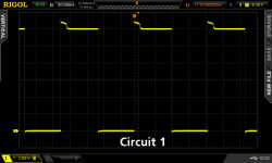
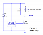
In "Circuit 1" below, the external terminals of the relay coil are clamped to 0.7V during flyback {but remember there is additional voltage drop internal, thanks to the coil's resistance}. In "Circuit 2" below, the external terminals of the relay coil are connected to a resistor + diode; the initial voltage is 0.7V + Icoil*Rexternal, and it follows an exponential decay. In "Circuit 3" below, the external terminals of the relay coil are connected to a Zener diode + PN diode; this clamps the external voltage to 15V (above the 12V supply). I measured this data using a 2N7000 MOSFET, and ICL-7555 chip, a 12V bench power supply, and this relay (12V coil, 16A contacts).
As the differential equation predicts, the higher the clamping voltage, the faster the turn off.
By the way, the smooth exponential decay of Circuit 2's waveform, includes an unexpected little "hump". This is due to the changing inductance of the coil as the armature's magnetic circuit changes, when it swings from the NO position to the NC position. It's not so visible in the other two circuits's waveshapes, which are binary square waves.
_
- V = L * delta_I / delta_T
- delta_T = L * delta_I / V
In "Circuit 1" below, the external terminals of the relay coil are clamped to 0.7V during flyback {but remember there is additional voltage drop internal, thanks to the coil's resistance}. In "Circuit 2" below, the external terminals of the relay coil are connected to a resistor + diode; the initial voltage is 0.7V + Icoil*Rexternal, and it follows an exponential decay. In "Circuit 3" below, the external terminals of the relay coil are connected to a Zener diode + PN diode; this clamps the external voltage to 15V (above the 12V supply). I measured this data using a 2N7000 MOSFET, and ICL-7555 chip, a 12V bench power supply, and this relay (12V coil, 16A contacts).
As the differential equation predicts, the higher the clamping voltage, the faster the turn off.
By the way, the smooth exponential decay of Circuit 2's waveform, includes an unexpected little "hump". This is due to the changing inductance of the coil as the armature's magnetic circuit changes, when it swings from the NO position to the NC position. It's not so visible in the other two circuits's waveshapes, which are binary square waves.
_
Attachments
-
 waves_3b.png26.9 KB · Views: 259
 -
 waves_3a.png27 KB · Views: 233
 -
 waves_2b.png25.3 KB · Views: 243
 -
 waves_2a.png28.2 KB · Views: 226
 -
 waves_1b.png25.4 KB · Views: 300
 -
 waves_1a.png25.1 KB · Views: 350
 -
 CIRCUIT_3.png19.3 KB · Views: 506
 -
 CIRCUIT_2.png19.2 KB · Views: 374
 -
 CIRCUIT_1.png17.2 KB · Views: 363
Mark, are you just deducing/estimating contact seperation time, or did you have a 2nd channel connected to the relay contact?
I have intentionally left that distinction to others. Fortunately it's just one IC, one MOSFET, and one relay on the protoboard, if anybody cares enough to run the experiment. Or, if that is way too much effort, perhaps manual interpretation (or SPICE simulation) might shed some light. Maybe it's worth a bit of thinking; but only if the answer is important.
As you highlighted, the waveform indication of a step in inductance as the moment when the pivoting armature separates from the coil core is the only tangible timing reference for when the spring loading pressure on the contact starts reducing, finally leading to contact separation.
I think it was Gigavac who did a fair bit of effort on their coil driver circuit to minimise the time to actual contact separation, taking in to account the different timing for the mechanical assembly to reduce pressure and finally cause contact separation, depending on rate of current decay in the coil. They also implemented a driver that reduced coil current once contact was made, providing a lower operating coil power loss, but also a lower current in the coil from which to turn off the relay.
I think it was Gigavac who did a fair bit of effort on their coil driver circuit to minimise the time to actual contact separation, taking in to account the different timing for the mechanical assembly to reduce pressure and finally cause contact separation, depending on rate of current decay in the coil. They also implemented a driver that reduced coil current once contact was made, providing a lower operating coil power loss, but also a lower current in the coil from which to turn off the relay.
Last edited:

Looks like I have some more reading to do 🙂.
I don't get it - Self on Audio is significantly cheaper as a paperback than as an ebook.
I don't get it - Self on Audio is significantly cheaper as a paperback than as an ebook.
- Status
- Not open for further replies.
- Home
- Amplifiers
- Power Supplies
- Snubbing a relay coil