I'm having a go at building my first valve mic , and looking at various circuits. The Sony C37 appealed because of it's simplicity and offboard output transformer, but there is one aspect that intrigued me - it's a Cathode Follower design but there is no capacitor between the cathode and the output transformer so there is a fairly high DC on the transformer. All of the non CF designs I have seen have a large high voltage capacitor blocking DC from the plate , and all CF designs I see in amps and have used myself have capacitors too. Is there any downside to this ? I'm assuming it doesn't affect sound quality or the mic wouldn't be as revered as it is , but does it change the tolerance of the winding wire used?


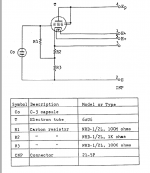
As far as I can see, there's a 6uF cap in series with the xformer, thus AC coupled.
Jan
Jan
The cathode (labelled "3") connects to a 6 uF capacitor. The transformer comes after that.
Good choice for a first experiment.
You'll need a preamp with a good amount of gain though.
Which kind of capsule do you plan to use?
You'll need a preamp with a good amount of gain though.
Which kind of capsule do you plan to use?
Whoops! Apologies all round , I was looking at the wrong number 3 pin , how embarrassing! In response to krivium I have a large diaphragm mic I can strip down and use the capsule from just to experiment with , probably a cheapish chinese one.Still wondering about the winding wire , I have been learning how to wind my own se output transformers and would like to have a shot- all I know about them is a comment on a forum from an owner saying they were almost the same size as amp output transformers.
Ok just things to be aware:
_all capsule won't work here. K67 (knockoff/copy) will sound (very) bright. K47 and ck12 kind worked quite well for my preference.
_ if you try to duplicate the circuit exactly you may not be able to use any of this capsule. Iirc the original b+ was very high for a mic ( 270v?) which gave around 100v for capsule bias. It's a lot and for the capsule (already mentioned) too high ( 60v will give better sound to me).
_ so a 6au6 could be exchanged. I used 5840 ( pentode subminiature, wired as a triode) and 150v b+ as a start ( i had a chinese psu availlable...) 60k/3,3k in the cathode, 100m for the grid and 2,2uf coupling cap. I've used lundahl1538xl and some line input transformer (ungapped, 10k:600r) ( both used backwards) as out transfo.
I settled on the lundahl but the much bigger line in was interesting too.
I had initially some noise. Traced the issue as heater/cathode leakage, referenced it ( heater voltage) to half psu rather than ground it cured the concern. Heater voltage was low at first iirc (~5,7v) because of poor quality cable. Switched to gotham cable and 6,3v was back.
Was nice on loud source with good capsule ( K47), load of headroom availlable. Often used it on drums, guitar amps ( with ck12 too)...
Thanks for that info,,,I was aware that the B+ is too high for most capsules , but thought I'd try reducing it to around 60v on the capsule. The one I've got is maybe wrong for this circuit , but that's ok , getting something that works and then improving it is the name of the game. I'll check out the lundahl.
Yes try it with what you have at hand.
The warning about the k67 is because when i tried it i thought it was an issue related to the circuit rather than the capsule... i was wrong.
That said you could like the effect ( this is what is used in C800G) and if you track voice very close miced some artists crave for that ( almost all rappers like C800G)..and as we routinely add high on voice at mix, why not integrate it directly at takes?
I prefer darker mic though (U67).
The lundahl i used with primary in paralell ( so backward 5:1). Very transparent transformer. The 10:1 was a Carnhill. Much much bigger. Less highs, more 'attitude' in the low and mids. But too much for what i was looking for.
Last edited:
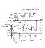
It's in there, badly drawn.there is no capacitor
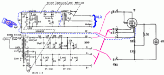
Mirror the mike-guts so the pins point to the power supply. (Or mirror the PS, but the mike is simpler.)
looking at the wrong number 3 pin
Yes, there are TWO EACH of pins 1 2 and 3. Realize that the audio transformer secondary is an XLR mike plug and ignore it.
Draw connecting lines.

Blue-dots is the mike audio path.
While it takes the long way around the bush, we see clearly what PFL200 spotted quickly: 6.8uFd in the power supply. Perhaps to keep its bulk and weight out of the can. Try to find photos: this may be a huge film-cap not a tiny e-cap.
To keep things confusing, the output terminal numbers don't match XLR pin numbers. On an XLR plug, 1 is ground, 2 is positive (hot) and 3 is negative (cold).
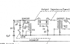
All your replies much appreciated , I have one more question regarding the filter setup. I am trying to figure out how the high-cut and low-cut work, making pretty poor attempts to model in LTSpice but I've only just started using Spice and I'm not sure how to represent a choke - if that is what it is , it does say "CH".
If it is , should it be common mode or differential? And possible value? There is an M followed by something , could be MilliHenries I suppose....
.
If it is , should it be common mode or differential? And possible value? There is an M followed by something , could be MilliHenries I suppose....
.

Hi,
Have you the mic manual? ( they give the response with filters engaged so will help to define your inductor values)
Here they are:
http://recordinghacks.com/microphones/Sony/C-37A
Anyway, i would first make a working example before try to implement filters ( which have very few interest in use in my view).
An interesting read about those kind of mics ( c12a, c800, c37,... tube cathode followers).
https://tapeop.com/tutorials/34/david-royer/
Last edited:
I didn't give enough explanation about your inductor: being passive filtering the outcome profile will be dependent of source and load Z ( impedance).
So even if you find the right values from simulation for the original schematic there is chance it won't work with your own version of the design ( it'll depend of the tube you'll use, bias you choose for it an the out impedance resulting from those choices).
So i would first make a working circuit and from there implement the filters. For low cut it is just a bank of caps, easy to go by trials and errors measuring outcome.
For high cut (if needed which i don't see why it could happen in this days of daw) then you'll need to define the out Z of your circuit ( and the load they'll usually see) to have a basis on which to implement the profile you want.
I hope it's clearer.
Hi , thanks for the response , and the links . I think you are right and I'll make a working model first (if I can) and look at the filters later if I think there's any value in them. I had seen the Royer article , it was what set me on the road of trying a cathode follower - although I hadn't envisaged how easily you get sucked in to getting obsessively involved with these things , I've got google-eyed searching through forum threads etc..!
There is no reason you won't succeed! I agree tube microphones are addictive...
One last thing if your capsule is dual sided ( allow multiple polar) study the way it is implemented in Akg C12a, it is an exemple of what Royer talk about in the article ( use of capacitor to grid).
If possible make the membrane 0v: you won't attract as much dust as if it is 60v biased. And clean all high impedance area ( the grid pin, the wires from the capsule, grid resistor). If possible use nitril non powdered gloves and isopropyl alcohol to clean flux and other nastys ( just be careful with membrane as they don't like alcohol...).
Last edited:
- Home
- Amplifiers
- Tubes / Valves
- Sony C37 Valve mic question