I need to replace some components of my M-Audio "Studiophile DX4" monitor speakers. But i have only partial information about the specs of the components I need to replace, and even less actual knowledge or understanding in general of the electronics involved. I'll share what I do know, and will make my questions as focused as I can on what I actually need to know and do to repair these things. I thank you very much in advance for any help:
The Problem(s): First, the left tweeter went silent. Then both sides developed a 100Hz hum ( I live in Israel, where the mains current is 230V and 50Hz). Then the left driver went silent also. I note that if I connect the right speaker directly to a mono source, it works just fine.
In addition to being silent, the left speaker got EXTREMELY hot when plugged in, which I suppose pointed to something being shorted out. I admit that when i tried to pinpoint things further, the main power transformer blew its internal thermal fuse. From what i can tell, I need to replace that as well as two caps that now are just open circuits.
The original configuration: what I know about the speakers is from two sources: Here is the block diagram from the M-Audio "user's guide":

There is also a detailed discussion of these speakers in this post to this site:
What I need to replace: a quick examination with multimeter has made it clear that at least one capacitor and the power transformer both need to be replaced. My questions are about these two components:
First about replacements for the power transformer:
The original has the following sticker on it only:

Question 1: I could not find anything about these spec numbers anywhere online. Could anyone tell me the specs of this transformer, or tell me how I could find them?
Lacking these, I learned from the post cited above to look at the data sheet for the TDA 2030 amplifier (which is fed by the diode bridge (which in turn is fed from the transformer)). This data sheet tells me that the "supply votlage" is +/-18V and that the "differential input voltage" is +/-15V. The post cited above only quotes the 18V number but says one needs a transformer rated at +/-13V.
Question 2: Do i need to get a center-tapped transformer which is rated no higher than +/-13V? Or can it be anything below +/-15V or even anything below +/-18V?
Question 3: Whatever the voltage rating, what other numbers do i need to specify for a suitable power transformer. Do I need to specify a maximum output current? What would this be and how do i know?
My next question is about finding a center-tapped transformer at all. I seem to be having difficulties finding one locally, and being heavy, shipping costs from abroad are very high. However, I have found two models locally that I think might do: One is called an MCTA and the other is called an MCFE transformer. Assuming that a datasheet/description in Hebrew wouldn't be very helpful here 🙂, here is a description of these two families of transformers from an English-language site:
MCFE: https://uk.farnell.com/multicomp/mcfe080-18/transformer-80va-2-x-18v/dp/9531831
"The Multicomp MCFE series are encapsulated toroidal transformers with flying leads. These transformers have a very high quality construction with high efficiency and smaller size compared to conventional EI transformers. MCFE series features a single primary winding rated at 230V 50/60Hz and dual secondary windings. Secondary windings can be connected in series or parallel or used independently."
This is from https://uk.farnell.com/multicomp/mcfe080-18/transformer-80va-2-x-18v/dp/9531831.
MCTA: https://uk.farnell.com/multicomp/mcta030-15/transformer-toroidal-2-x-15v-30va/dp/9530312?st=mcta
"The MCTA030/15 from Multicomp is a general purpose toroidal transformer with flying leads. It is designed and manufactured in accordance with EN61558-1 / EN61558-1/A1 /EN61558-2-4 or EN61558-2-6 UL recognised under family approval E115159 to UL1411, UL60601-1 and UL60065-1."
Question 4: I can find locally either of these transformers at various specs. Am I completelty off, or could I use one or the other in place of the center-tapped transformer from the original?
Next, I turn to a capacitor which seems to be blown and need to be replaced:
The cap is soldered onto the two sides of the On/off switch. (Obviously, the two leads from the mains input are also soldered onto the two sides of the switch). Here is a pic of this cap (which is now just an open circuit):

I understand that it's a 47picoF / 250V cap, and they had none at the shop. They did have in stock some 22picoF/250V caps, like this:

(I see that the pic is displayed upside-down, and I apologize for this. But I have had GREAT trouble editing this post without somehow getting it posted before it's ready, so I will ask your forgiveness that I don't press my luck and try to edit the attached pic to be right-side up. I hope it is legible as is).
Question 5: It seems to me that if I solder TWO of these things identically, with one contact on each of the two sides of the On/Off switch, I will have put 44picoF of capacitance there. Is this a good enough replacement for the original 47picoF in one cap? (I'd also love to learn what this capacitor is doing here, anyhow. But that's less important than learning if it's ok to put in the two caps to replace the one that is an open circuit).
For all the other blown components I can find simple and "perfect" replacements.
Thanks for help, especially for understanding what i can use to replace that non-functional power transformer.
scott
The Problem(s): First, the left tweeter went silent. Then both sides developed a 100Hz hum ( I live in Israel, where the mains current is 230V and 50Hz). Then the left driver went silent also. I note that if I connect the right speaker directly to a mono source, it works just fine.
In addition to being silent, the left speaker got EXTREMELY hot when plugged in, which I suppose pointed to something being shorted out. I admit that when i tried to pinpoint things further, the main power transformer blew its internal thermal fuse. From what i can tell, I need to replace that as well as two caps that now are just open circuits.
The original configuration: what I know about the speakers is from two sources: Here is the block diagram from the M-Audio "user's guide":
There is also a detailed discussion of these speakers in this post to this site:
What I need to replace: a quick examination with multimeter has made it clear that at least one capacitor and the power transformer both need to be replaced. My questions are about these two components:
First about replacements for the power transformer:
The original has the following sticker on it only:
Question 1: I could not find anything about these spec numbers anywhere online. Could anyone tell me the specs of this transformer, or tell me how I could find them?
Lacking these, I learned from the post cited above to look at the data sheet for the TDA 2030 amplifier (which is fed by the diode bridge (which in turn is fed from the transformer)). This data sheet tells me that the "supply votlage" is +/-18V and that the "differential input voltage" is +/-15V. The post cited above only quotes the 18V number but says one needs a transformer rated at +/-13V.
Question 2: Do i need to get a center-tapped transformer which is rated no higher than +/-13V? Or can it be anything below +/-15V or even anything below +/-18V?
Question 3: Whatever the voltage rating, what other numbers do i need to specify for a suitable power transformer. Do I need to specify a maximum output current? What would this be and how do i know?
My next question is about finding a center-tapped transformer at all. I seem to be having difficulties finding one locally, and being heavy, shipping costs from abroad are very high. However, I have found two models locally that I think might do: One is called an MCTA and the other is called an MCFE transformer. Assuming that a datasheet/description in Hebrew wouldn't be very helpful here 🙂, here is a description of these two families of transformers from an English-language site:
MCFE: https://uk.farnell.com/multicomp/mcfe080-18/transformer-80va-2-x-18v/dp/9531831
"The Multicomp MCFE series are encapsulated toroidal transformers with flying leads. These transformers have a very high quality construction with high efficiency and smaller size compared to conventional EI transformers. MCFE series features a single primary winding rated at 230V 50/60Hz and dual secondary windings. Secondary windings can be connected in series or parallel or used independently."
This is from https://uk.farnell.com/multicomp/mcfe080-18/transformer-80va-2-x-18v/dp/9531831.
MCTA: https://uk.farnell.com/multicomp/mcta030-15/transformer-toroidal-2-x-15v-30va/dp/9530312?st=mcta
"The MCTA030/15 from Multicomp is a general purpose toroidal transformer with flying leads. It is designed and manufactured in accordance with EN61558-1 / EN61558-1/A1 /EN61558-2-4 or EN61558-2-6 UL recognised under family approval E115159 to UL1411, UL60601-1 and UL60065-1."
Question 4: I can find locally either of these transformers at various specs. Am I completelty off, or could I use one or the other in place of the center-tapped transformer from the original?
Next, I turn to a capacitor which seems to be blown and need to be replaced:
The cap is soldered onto the two sides of the On/off switch. (Obviously, the two leads from the mains input are also soldered onto the two sides of the switch). Here is a pic of this cap (which is now just an open circuit):
I understand that it's a 47picoF / 250V cap, and they had none at the shop. They did have in stock some 22picoF/250V caps, like this:
(I see that the pic is displayed upside-down, and I apologize for this. But I have had GREAT trouble editing this post without somehow getting it posted before it's ready, so I will ask your forgiveness that I don't press my luck and try to edit the attached pic to be right-side up. I hope it is legible as is).
Question 5: It seems to me that if I solder TWO of these things identically, with one contact on each of the two sides of the On/Off switch, I will have put 44picoF of capacitance there. Is this a good enough replacement for the original 47picoF in one cap? (I'd also love to learn what this capacitor is doing here, anyhow. But that's less important than learning if it's ok to put in the two caps to replace the one that is an open circuit).
For all the other blown components I can find simple and "perfect" replacements.
Thanks for help, especially for understanding what i can use to replace that non-functional power transformer.
scott
Attachments


The cap in your picture is a 4700pF (472 = 47 and two zeros). Those caps rarely fail and should read totally open circuit on multimeter. Any replacement must be 'Class X' or Class Y' rated and suitable for 250 Volts AC working. The 'M' represents 20% tolerance.
Safety Capacitors First: Class-X and Class-Y Capacitors
The small WIMA caps you show are NOT suitable for mains use even though the 650 V AC rating suggests otherwise.
Assuming your TDA2030's are running on -/+ 18 volts DC then you need a transformer of 18/root 2 or 18/1.414 which is really a 12-0-12 volt AC transformer.
It needs to be centre tapped (12-0-12) or have to separate windings which can be series connected (12-0, and 12-0) which would make up the equivalent of a 12-0-12.
An 80 or 100va rating would cover anything a TDA2030 output stage could attempt to deliver.
The amplifier fault sounds like blown output chips which shorted the power supply and caused the transformer to overheat. You should also check the power supply components such as bridge rectifier and reservoir caps for failure/deterioration.
I see ( i think). OK, so I can resolder the original cap on to the posts of the on/off switch. You are completely correct about what I think are the reservoir caps and the bridge rectifier -- these are the components that I alluded to in my original post when I said I could find "perfect" replacements for them.
Could I ask if either the MCTA or the MCFE transformers of my original post qualify as having separate windings which can be series connected? I think that they are, it's just that this is my first time out and I don't have anyone local I can ask. I feel that your first answer to me already has corroborated what I first suspected, which is that the local electronics shop is unwilling, uninterested, or incompetent to help a newbie fix (rather than destroy) his equipment; so I truly appreciate a check if either one of the MCTA or MCFE transformers i gave a link to above will work. (Obviously, I need to make sure the voltage is 12-0 and 0-12 and not something else).
Thanks also btw about the root 2 factor; that's obviously what I had not understood before.
Yes, both those series of transformers have separate secondary's which can be series connected.
This will help identifying secondary windings if you ever need to do this:
How to wire transformer
This will help identifying secondary windings if you ever need to do this:
How to wire transformer
The amplifier fault sounds like blown output chips which shorted the power supply and caused the transformer to overheat. You should also check the power supply components such as bridge rectifier and reservoir caps for failure/deterioration.
My questions are to make sure I understand which are the "output chips" and "reservoir caps". Please bear with me:
A "bird's eye" view of the electronics shows two sides with a metal wall down the middle. I'm guessing the left side handles "power" and the right side does the actual audio amplification. The TDA3020 chips are attached to the "amp side" of dividing wall itself, with their pins soldered on amp side of the divide. There are also two 4558D JRC 5028B (opamp) chips on the amp side of the divide. So:
1. By "output chips" do you mean the TDA3020 or the 4558D JRC5028B (or both)?
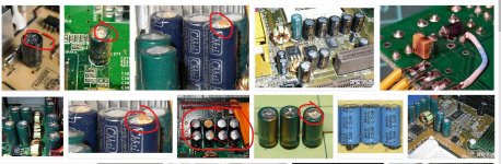
2. Are the "reservoir caps" the big cylindrical ones right where power enters, next to the recitifier diode bridge? (the two big cylndrical caps at the left of the above picture, with the metallic ends and a blue ring that continues down the sides of the cylinder. You can see two red wires which bring power to the board to the left of those large caps; there is a black wire in between the two red ones. These are the wires from the three taps of the center-tapped transformer). I definitely see these caps charge up when i apply a multi-meter. Is that a good enough test, or do I need to do something more precise?
I thought I would post pictures of the "output" components in question to be double-sure.... and LOOK WHAT I FOUND (this is sort of embarassing): here is a pic of the TDA3020 chips against the metallic wall:
Both chips seem to have been in an earthquake. Does this damage imply that I should stop right now, because everything else will also be damaged beyond repair?
Here is the best pic I could get of the 4558D JRC 5028B chips. Note the tiny perfect circle indentation in both chips in the lower left-hand corner. Is this normal, or also a sign of extreme damage?
Finally, you can see that some of the round caps look as if they had brown-black 'hair' 'on the tops of their heads. Is this further damage or normal?
scott
Attachments


The TDA's exploding is absolutely typical of what happens and there is no reason to think anything else would damaged, particularly as you say you can see the caps charging OK.
It is possible those two big caps (reservoir caps) might have deteriorated, although often the top of the can bulges when they do as the vent splits open. Without equipment to test them its simplest just to replace them with new if there is doubt. There is a good chance yours are absolutely fine but it was worth mentioning that they can deteriorate as they have a hard life.
When repairing something like this you should use a 'bulb tester' wired into the transformer primary circuit which will limit current and prevent damage. Use a 40 or 60 watt filament bulb.
ok, I read about the bulb tester and can see that I'm going to learn a lot doing this little project.
I take it from your lack of even relating to my two other questions that I don't need to worry about them:
1. the little 'circular depression' at the lower left of both of the opamp chips (JRC 4558D in the pic above). Normal or a sign of damage?
2. In the same pic, there are several small orange capacitors which look like "little orange men with heads and legs but no bodies (one in the pic has a big "22" stamped on its "face"). Some (but not all) of these orange capacitors have nice neat black/brown "hair" on top of their heads. (they're "Orange caps with a cap of brown-black hair" as it were 🙂). Is this brown-black top normal or a sign of damage?
I might as well ask (though if i am stepping into a religious war that is not my intention): I know that some of these capacitors come in "expensive" hifi audio versions. If I do need to replace some, should I always/sometimes/never go for the 'special' ones that cost a lot more. (And equally obviously, if the answer is 'sometimes', which ones deserve the special treatment and which ones don't? How do i decide?)
thanks again for all this help. I would have no chance to succeed without it.
scott
🙂
The round depression identifies pin #1 of the chip which we need to know in order to orientate it correctly. The markings vary from manufacturer to manufacturer and may simply identify that 'end' of the chip, pin #1 always being the lower left one.
The caps 😉 I couldn't see what you meant and thought you were looking at electrolytics tbh. Right then... so these are small 'compressed disc' ceramics and the black haircut is the temperature range it can operate under which I think is -25C to +85C for these. The 22 will be the value, 22pF. If it was 471 it would be 47 and one zero meaning 470pF. A 1000pF would be 102 and so on.
There is no such thing as a 'Hi Fi' capacitor. A capacitor should always be selected on its merits... good brand, suitable type, suitable temperature range, and for arduous duty such as reservoir caps or caps in switching supplies you need to look at ripple current ratings and E.S.R. (equivalent series resistance).
Edit...
Here you go:
Ceramic Disc Capacitor Values / Code / Label
Edit edit…
This one is quite good:
Basics: Finding pin 1 | Evil Mad Scientist Laboratories
OK, I have obviously been given enough information that i need to shut up and start ordering. It may be two weeks before I post here again, but that's only because I'll be actually doing something rather than merely asking YOU to do something (ie. give me information). wish me luck. Wish my neighbors luck too (that i shouldn't blow them up as well).
Sorry that I was mistaken. But my questions will show that im doing something, at least.
Ok so I've just soldered a new diode bridge rectifier and the cap that goes with it. These two parts:
I know that the rectifier has an orientation (!) and that I need to solder it in the correct orientation (!!). My question is about the little brown cap. As far as I can tell, I am soldering that into contact with the two middle pins of the rectifier. Does the brown cap have an orientation? If so, how do I tell what it is, and what does it need to be?
Thanks
Scott
Attachments

The little cap would have almost certainly been OK as they are generally super reliable. Its a small polyester/metalized film type and is not polarity conscious. So any way around. It serves to reduce electrical interference from the diode bridge (switching or commutation noise) as the diodes drop in and out of conduction on each half cycle.
All the King's horses and all the King's men.....
Perhaps even more appropriately is the Japanese proverb: "it can take 1000 wise men to remove the stone from a well that took one single fool to throw in....."
I feel so stupid, but it seems that I didn't properly document how things were originally connected. Here are three pics which show the things that need to be connected. Any chance you can help me?


In particular: the relative size of the red and black connector tells me for certain how to connect the black connector. But there seems to be two connectors of the correct size for the v Ted connector. Since the red and black wires come from the main driver, I'd guess that the red connector should be connected to the "L-OUT" connector on the circuit board. But then what is the purpose of the connector in the corner of the circuit board? There seems to be no wire to connect to it!! Have I lost a connector wire somewhere?
(The white plugs are of different sizes and are their idiot-proof.
Scott
Perhaps even more appropriately is the Japanese proverb: "it can take 1000 wise men to remove the stone from a well that took one single fool to throw in....."
I feel so stupid, but it seems that I didn't properly document how things were originally connected. Here are three pics which show the things that need to be connected. Any chance you can help me?
In particular: the relative size of the red and black connector tells me for certain how to connect the black connector. But there seems to be two connectors of the correct size for the v Ted connector. Since the red and black wires come from the main driver, I'd guess that the red connector should be connected to the "L-OUT" connector on the circuit board. But then what is the purpose of the connector in the corner of the circuit board? There seems to be no wire to connect to it!! Have I lost a connector wire somewhere?
(The white plugs are of different sizes and are their idiot-proof.
Scott
Attachments


- Status
- Not open for further replies.
- Home
- Amplifiers
- Power Supplies
- specs / replacement for a center-tapped transformer of an M-Audio DX4 Speaker pair