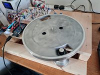
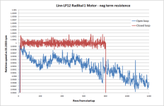
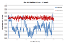
Hi all. I bought a RE max motor from maxon last year and have now got it running on a test rig I put together. The motor will be going in my LP 12 in due course and the rig is being used to develop the drive circuit, control parameters and to check all is well with the motor. In the rig the motor runs super slow with a drive ratio around 10x. There is no noise or vibration evident from the motor, which is good. The drive circuit is on a breadboard arduino controlled driving a voltage dac which provides 0 to 4 volts with a resolution around 20 bit so there is amble resolution to control the motor. Previous experience I have is that closed loop feedback is needed and negative terminal resistance, to both keep the speed accurate and to deal with stylus drag. Testing on this motor confirms the same. I have tested open and closed loop with and without negative resistance. The graphs show the effect on speed stability for these configurations. Note the drift in open loop is just over 1000 revs starting it off on point, so could degrade further thereafter.
The best accuracy is around plus / minus 0.01% at 33rpm. How does this compare to other motor types?
The best accuracy is around plus / minus 0.01% at 33rpm. How does this compare to other motor types?
Attachments

Have you measured the variability of the Hall sensor threshold in terms of rotation angle? It might be a source of measurement noise if you're trying to look at 0.01% or so (which is 2 minutes of arc, or 0.1mm at the platter's edge)
Make sure your Arduino has a quartz crystal, not a ceramic resonator if you want high accuracy timing measurements.
Make sure your Arduino has a quartz crystal, not a ceramic resonator if you want high accuracy timing measurements.
Thanks for that I had not thought the resolution of the speed error was that small. I don’t know how to determine variability in the hall sensor. There is nothing in the datasheet indicating that parameter. The arduino has a crystal oscillator and the micros function has a resolution of 4 microseconds which equates to 0.0002% error at 33rpm, so that seems good enough. It may be worth trying an optical sensor to see if that is better.
Hi deano, I really like what I see for the speed control. Did you end-up using a pcb or stocking withe breadboard? The last circuit diagrahm you included is that the final version? Curious, as I am trying to make my own speed controller with the similar parts & and I am no engineer or designer by any stretch of the imagination!