I am making progress fixing and "calibrating" this classic calibrator.
![20240615_061313[1].jpg](https://www.diyaudio.com/community/data/attachments/1230/1230331-7749f363850d50b7429ecebeea2ccb01.jpg "20240615_061313[1].jpg")
Backstory:
(or skip down to the maroon coloured text to see my concerns/issues}
I am attempting to rehab a 70's FM tuner (Luxman t110u).
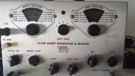
So, I found this dusty Sound Technology ST1000A at my local surplus dealer - no fuse holder, loose switches, unknown functionality.... $100.
At my bench, I fixed the fuse and decided to replace the main PSU filter caps. Good thing, because one of them was bad and had turned into a wayward resistor.
(they were 1500uf each rail, but I went for 2000uf each.)
![20240615_063802[1].jpg](https://www.diyaudio.com/community/data/attachments/1230/1230333-180860dd6a36c988ab867ff5dadf1959.jpg "20240615_063802[1].jpg")
Then, through an ammeter, I plugged it in to my variable AC transformer, flipped the ST1000a power switch and slowly turned the voltage up to 120v ...keeping a close eye that the ammeter did not spike.
All seemed ok, and it showed signs of life.
After a long sleep, it curiously opened it's dusty eyes.
I cleaned and lubed the rotary switches. The carbon pots did not seem to need attention. The meter reacted as if it was new.
I began to replace the smaller axial electrolytic caps on the internal board, but every cap I removed tested like new, so I stopped replacing them, for now. Those old Sprague 30D types seem pretty robust !
This must be an early unit, because it includes Opt, M-2, but not with the typical 1k/400hz switch.
Instead, it has 4k/400hz. Curious.
![20240615_064104[1].jpg](https://www.diyaudio.com/community/data/attachments/1230/1230342-c08e65331be996741129974f08d72c0e.jpg "20240615_064104[1].jpg")
The manual/service guide is easily found online, and here...... http://www.stancurtis.com/soundtech.htm
An article on "updating/upgrading" the ST1000a is here..... http://www.ham-radio.com/k6sti/st-1000a.htm
Following the adjustments outlined the manual, the ST1000a was close to specs, but everything needed a little tweaking to become spot-on.
I performed one upgrade from the above article, to lower the distortion of the internal wein-bridge oscillator (added two resistors and a cap).
Using my QA403 audio distortion analyzer, before the mod :
3862 Hz (4 kHz) = .027 %THD
393 Hz (400 Hz) = .017 %THD
...after the mod:
3862 Hz (4 kHz) = .0008 %THD
393 Hz (400 Hz) = .0006 %THD
Other adjustment steps from the manual:
152 kHz/19 kHz Crystal oscillator adj.... (C20) adjusted to within 10hz, good.
R/L Gain Balance (38kHz Carrier Suppression) (R1, R7) One trim pot minimizes the 38khz ripple from the upper half of the (sine) waveform, another trimmer does the same to the lower half of the waveform. I think I did it correctly, making both halves of the sinusoidal wave show as little ripple as possible. I can still see a little ripple, but just barely.
DC balance. (R19) Trim to get lowest DC millivolts (less than 20mV) I trimmed to 5mV.
Mono/Stereo Sub-channel Separation. (R35, R38) Here, the guide is confusing. I don't feel confident that I am adjusting correctly.. or to what is wanted.
The drawings are rather vague ?
![20240615_082954[1].jpg](https://www.diyaudio.com/community/data/attachments/1230/1230366-230bf113077ad4186604385d398057c3.jpg "20240615_082954[1].jpg")
I tried Method A and Method B.
Method A, I think I'm trying to get the flattest line across the center ?
Method B, I think I'm trying to get the "cusps" close, but not touching ?
Here are my adjustments, and a pic of the overload-preventing clipping diodes, per the manual instructions:
![20240614_215546[1].jpg](https://www.diyaudio.com/community/data/attachments/1230/1230376-1c1e745df7f2e466bdb69a0c09f55cdf.jpg "20240614_215546[1].jpg")
![20240614_215947[1].jpg](https://www.diyaudio.com/community/data/attachments/1230/1230378-e960e0c16dbbef0cec2b25fd3b0a2551.jpg "20240614_215947[1].jpg")
![20240615_082558[1].jpg](https://www.diyaudio.com/community/data/attachments/1230/1230379-6e98eca27e0adee62d4a01c1e91ff4bd.jpg "20240615_082558[1].jpg")
FM Modulator Linearity. (trimmer R52) In this step, I do not have the gear shown in the drawing.
HP 5210a Discriminator
HP 10534a Double Balanced Mixer (50k to 150mHz)
![20240615_063825[1].jpg](https://www.diyaudio.com/community/data/attachments/1230/1230385-096e1cbccd9ea13601001457b856af13.jpg "20240615_063825[1].jpg")
The 5210a discriminator...guessing this gives you the difference between two frequencies ??
I think I can do that with my counters, including phase differences ?
![20240614_224040[1].jpg](https://www.diyaudio.com/community/data/attachments/1230/1230388-eee41212464154b13be85bb181b40b98.jpg "20240614_224040[1].jpg")
The HP 10534a passive mixer....I have one of these (Clarke Hess "active" mixer) but I'm not sure if will work, or if it has enough bandwidth , I've been looking for it's rare manual.
![20240614_224050[1].jpg](https://www.diyaudio.com/community/data/attachments/1230/1230389-20861a7eec4a9f9190d8f9aa06fdc727.jpg "20240614_224050[1].jpg")
Modulator Level (trimmers R47, R95) This is to be done after the above Linearity step, so I can't proceed before the Linearity adjustment.
The manual gives a method using an accurate Standard Generator, OR a method for using a Discriminator.
Internal Oscillator (distortion adjustment, R105, R95) I did that, as noted earlier.
Pilot Phase. (R93) not adjusted yet.
L/R Balance (R118) not adjusted yet.
RF Stereo Separation (C16 trimmer) not adjusted yet.
END OF ADJUSTMENTS.
BTW, I built the "ST Model 100" 50 ohm to 300 ohm adapter, as noted from the links above....
![20240615_064006[1].jpg](https://www.diyaudio.com/community/data/attachments/1230/1230400-63a351e4340e9c5686399d1e7d5dd342.jpg "20240615_064006[1].jpg")
Backstory:
(or skip down to the maroon coloured text to see my concerns/issues}
I am attempting to rehab a 70's FM tuner (Luxman t110u).
So, I found this dusty Sound Technology ST1000A at my local surplus dealer - no fuse holder, loose switches, unknown functionality.... $100.
At my bench, I fixed the fuse and decided to replace the main PSU filter caps. Good thing, because one of them was bad and had turned into a wayward resistor.
(they were 1500uf each rail, but I went for 2000uf each.)
Then, through an ammeter, I plugged it in to my variable AC transformer, flipped the ST1000a power switch and slowly turned the voltage up to 120v ...keeping a close eye that the ammeter did not spike.
All seemed ok, and it showed signs of life.
After a long sleep, it curiously opened it's dusty eyes.
I cleaned and lubed the rotary switches. The carbon pots did not seem to need attention. The meter reacted as if it was new.
I began to replace the smaller axial electrolytic caps on the internal board, but every cap I removed tested like new, so I stopped replacing them, for now. Those old Sprague 30D types seem pretty robust !
This must be an early unit, because it includes Opt, M-2, but not with the typical 1k/400hz switch.
Instead, it has 4k/400hz. Curious.
The manual/service guide is easily found online, and here...... http://www.stancurtis.com/soundtech.htm
An article on "updating/upgrading" the ST1000a is here..... http://www.ham-radio.com/k6sti/st-1000a.htm
Following the adjustments outlined the manual, the ST1000a was close to specs, but everything needed a little tweaking to become spot-on.
I performed one upgrade from the above article, to lower the distortion of the internal wein-bridge oscillator (added two resistors and a cap).
Using my QA403 audio distortion analyzer, before the mod :
3862 Hz (4 kHz) = .027 %THD
393 Hz (400 Hz) = .017 %THD
...after the mod:
3862 Hz (4 kHz) = .0008 %THD
393 Hz (400 Hz) = .0006 %THD
Other adjustment steps from the manual:
152 kHz/19 kHz Crystal oscillator adj.... (C20) adjusted to within 10hz, good.
R/L Gain Balance (38kHz Carrier Suppression) (R1, R7) One trim pot minimizes the 38khz ripple from the upper half of the (sine) waveform, another trimmer does the same to the lower half of the waveform. I think I did it correctly, making both halves of the sinusoidal wave show as little ripple as possible. I can still see a little ripple, but just barely.
DC balance. (R19) Trim to get lowest DC millivolts (less than 20mV) I trimmed to 5mV.
Mono/Stereo Sub-channel Separation. (R35, R38) Here, the guide is confusing. I don't feel confident that I am adjusting correctly.. or to what is wanted.
The drawings are rather vague ?
I tried Method A and Method B.
Method A, I think I'm trying to get the flattest line across the center ?
Method B, I think I'm trying to get the "cusps" close, but not touching ?
Here are my adjustments, and a pic of the overload-preventing clipping diodes, per the manual instructions:
FM Modulator Linearity. (trimmer R52) In this step, I do not have the gear shown in the drawing.
HP 5210a Discriminator
HP 10534a Double Balanced Mixer (50k to 150mHz)
The 5210a discriminator...guessing this gives you the difference between two frequencies ??
I think I can do that with my counters, including phase differences ?
The HP 10534a passive mixer....I have one of these (Clarke Hess "active" mixer) but I'm not sure if will work, or if it has enough bandwidth , I've been looking for it's rare manual.
Modulator Level (trimmers R47, R95) This is to be done after the above Linearity step, so I can't proceed before the Linearity adjustment.
The manual gives a method using an accurate Standard Generator, OR a method for using a Discriminator.
Internal Oscillator (distortion adjustment, R105, R95) I did that, as noted earlier.
Pilot Phase. (R93) not adjusted yet.
L/R Balance (R118) not adjusted yet.
RF Stereo Separation (C16 trimmer) not adjusted yet.
END OF ADJUSTMENTS.
BTW, I built the "ST Model 100" 50 ohm to 300 ohm adapter, as noted from the links above....

That is correct.Method A, I think I'm trying to get the flattest line across the center ?
