I would like to make adaptors for using sub-miniature tubes in regular 9 pin sockets, so that I could compare the performance of sub-minis with their 9 pin tube brethren.
The 8 pin bases are readily available, for example:
10pc bakelite octal 8pin tube base for 6sn7 el34 power plug | eBay
I’m looking for a base that would plug into a standard 9pin socket, to solder the flying leads of the sub-mini tube to. Problem is I can seem to find any “naked 9 pin bases” for sale. Could someone help?
Problem is there were no bases on the 9-pin tubes, the pins were part of the tube. Though I am sure some still call them that.
Common 9-pin tubes are called Noval. Google noval tube plug and see some possibilities. They sell "socket savers" around, which is basically a 9-pin plug with a socket on top. Plug the saver into your amp socket then wear out the saver's socket changing tubes. You could probably adapt some of those.
here is one:
1PC 9PIN TO 9PIN Tube DIY Audio Vacuum Tube Adapter Socket Converter Soft foot valve conversion Vacuum Tube Amplifier DIY|socket wifi|socket a cpu coolersocket head cap screw grades - AliExpress
Have those sub-minature tubes got a designation ?
I have made very many conversions of earlier tube testers where the bases weren't enough for all types but now I have an AVO MKIV VCM it has a base for flying leads as they are called in the UK.
I take it you are talking about B9A plugs which is the standard designation in the UK & EU ?
Okay I have got a German company that sells "Noval " (B9A ) --one to one adapters easy job just to cut off the top and solder the fyling leads to the bottom half .
Noval Zubehör - BTB Elektronik
If so-
NOS B9A plugs | #269084076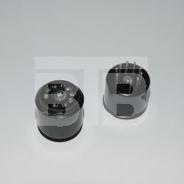
Last edited:
Enzo and duncan2,
Thank you both for your help and comments.
The problem with the 1:1 Noval tube savers that I have bought is that the pins go 1:1, with a single connector that goes from the socket side (top) to the pin on the bottom. As a result you can not easily switch and solder the leads to the adapter - they are made for plugging the same tube into the adapter as was originally intended for the socket being saved. Additionally, if you cut of the connector at the top, the pin at the bottom is loose without a way to attach it to the base. This seems to be the case with the BTB Elektronik device.
Perhaps the adaptor from VIC-Audio that Enzo pointed out, or something similar will allow me to solder the flying leads to the PCB, making the correct connections.
Last edited:
When making tube adapters for a smaller tube/valve tester before I bought my large one it was always the case that you had to wire some slightly differently depending on the base but in a tube tester it was only the exotic kind as you are able to apply different conditions to every tube base by switches .
In a fixed use like you want then certain conditions exist --most (but not all ) B9A bases have the heaters on -
Pins- 4&5 that is an industrial standard.
the anode (plate ) on -
Pin-6
Then you have variations ,
It was no big deal to solder wires to individual pins and in your case as it will be usually audio type tubes you will be using in your audio circuits then just wire up your favorite tubes .
it isn't rocket science it just takes a bit of time .
Pin connections are easily obtainable online if you don't have tube/valve equivalent books.
I remember seeing glass bases for sale a few years ago. If they're around OK, but you could take an old tube and cut off the base.
You could also make your own base using pin sockets like these. (Check the dimensions. I think I got them right but I'm tired and take no blame.)
Just make a (thin) board for the Noval circle and push the pin receptacles right through. (Make sure you don't get any solder inside.)
If doing it to check things out on a finished 9 pin circuit and not for permanent use I'd probably just push the pin receptacles into the 9 pin socket. Then plug the submiini leads into the receptacles.
The precaution I take is to put some insulation from stripped hookup wire on the submini's leads as you'll have to cross leads at some point and it's just easier not to have to worry about them touching .
I throw all the insulation into a can on the bench so can usually find some green for heater, blue for cathode, white for grid, red for plate. It means you only have to look at the data sheet for the submini once and the rest of the time you can stay focused on matching the leads to the pin-out for the 9 pin you're replacing.
Be careful. It's easy to make things touch that shouldn't.
HTH
Thanks again for your help kind audiogentlemen. duncan2, I have no problem figuring out the correct connections but needed help with selecting the correct parts to make an adapter.
Thank you Hearinspace for your help. That reference to the Digikey item got me on the right track for the male pin size. I now plan to use these PCBs and solder the pins in, while making the correct flying lead connections on the perimeter.
5pcs PCB Adapter Board CMC 9 Pin Tube Socket For 9 pin ECC83 12AX7 EL84 6BQ5 6N1 | eBay
Similar to previous octal connections but with the Noval pins to plug right into the original socket.
Attachments

If it were me I would cut up an old computer male DB connector an use the pins from that rather buying new pins.
I came to socket savers with the idea of cutting them open and using them as the basis for your project.
If it were me I would cut up an old computer male DB connector an use the pins from that rather buying new pins.
I wished to be able to “roll” the sub-mini’s with their corresponding novals, without having to change anything, so I needed a way to directly plug a sub-mini tube into a noval socket.
Enzo, I bought some socketsavers, but what I got had a “straight thru“ pin that has the socket at the top, and it is the socket-side that holds it in place. If you cut the socket, the pin is loose to fall out of the base
Last edited:
I wished to be able to “roll” the sub-mini’s with their corresponding novals, without having to change anything, so I needed a way to directly plug a sub-mini tube into a noval socket.
I know that. I mean I would use those PCB adapters, but not buy new pins from Digikey, but use the pins from a DB connector.
Just in case I have picked you up wrongly here you are talking about "sub-miniature "--WIRE ended tubes as shown in post #7--yes ?
You then say the "straight through " adapter is pin to pin compatible--
IE- Pin 1 to Pin 1 ,what then is stopping you soldering the top/input sockets in any arrangement you like as the wires of the sub-miniature tube are flexible ,it might not look too professional but electrically it would work ?
In other words if Pin 1 is Plate 1 then the wire on the sub-miniature tube that corresponds to the Plate is soldered to Pin 1 and so on .
All done without any cutting up or dismantlement.
I had a much harder job when making up tube base converters as I made them from scratch using rigid copper wires so that the top base would not move or shake , this involved some criss-crossing of the pins
to suite some unusual tubes ,soldered at both ends .
As I said it wont look good but it works but takes time.
duncan2, you are correct, I could solder the flying leads to the top of the “saver” to the correct socket/pin. Since several of the flying leads will be crossing, I probably need tubing. That is why I thought the small PCBs I mentioned in #7 might be a better (and cheaper) solution, since the flying lead connections are soldered on the outside perimeter.
- Home
- Design & Build
- Parts
- Sub-mini to 9 pin base