Hi
I recently have built a 250W mosfet amplifier and I need a very good Low pass filter ( Sub filter ) for it to drive my sub
I tried this one
Low pass filter - Subwoofer

but I want something with higher performance
Please introduce me something that you've built and it did work
thanks
Please someone give me a reliable and tried schematic😕
I recently have built a 250W mosfet amplifier and I need a very good Low pass filter ( Sub filter ) for it to drive my sub
I tried this one
Low pass filter - Subwoofer
but I want something with higher performance
Please introduce me something that you've built and it did work
thanks
Please someone give me a reliable and tried schematic😕
That's a standard unity gain Sallen-Key filter set up for LR2 which should work if properly implemented. An issue is that if the dual pot sections don't track well you could have some response irregularities. What are the performance issues that you would like to improve? What crossover frequency are you targeting? Are you high passing the mains? What is the mains F3?
Take a look at Active Filters for proven circuits. Use a decent regulated power supply and OPA2134 or better. Be sure to bypass the opamps power connections with 100 nF right at the chip.
EDIT: Actually for sub duty, you don't really need OPA2134, you can get away with even a TL072, although the cost differential is only a couple dollars.. Use better op amps on the high pass section if you build one.
I'd start with an input buffer like the circuit surrounding IC1 in your circuit, except use a fixed 47K resistor for R3. You need this to mix the two channels (assuming that this is a stereo project and not HT receiver is involved.)
Then add a standard Sallen-Key filter stage or two, depending on your target slope and an adjustable attenuation drive to the output buffer. The adjustable attenuation can be as simple as using your 47K pot as a normal volume control. You can also use it as a variable series resistor with a 10K resistor to ground across the input of the buffer. This would give you greater precision of adjustment over a +10to -5 dB range. (with R3 = 47K you will get 10 dB gain in the buffer. If this is too high, simply reduce it to 20K and you will have roughly 0 gain to -15 db.)
Last edited:
Thank you for your attention
my amp has these characteristics :
POWER RATING at 1KHZ with 0.1* THD = 200W/ 8 ohm, 260W /4 ohm
IMD= *0.008*
THD at 200W into 8 ohm *1 KHZ= *0.005*
THD at 200W into 8 ohm *20 HZ....20 KHZ= *0.05*
FREQUENCE RESPONSE [at 50W/8ohm, *0...-3dB]= 1.5 HZ.....125 KHZ
INPUT SENSITIVITY= 1Vrms
ΙΝPUT IMPEDANCE= 48K
SLOW RATE with input filter= 20V/uS
=SIGNAL TO NOISE RATIO [at 1W/8ohm] *99dBA
= DAMPING FACTOR at 8ohm [15HZ...25KHZ] 160
And I need a Sub filter for it
I tried upper circuit but it has a little noise on it ( I can hear a little voice of the singer on a music ( just a little ) when just subwoofer is working) and I think the output of this circuit is not enough for my input amplifier ( 1V rms ) do I need a preamp for this ?
I want something in the range of 30- 160 Hz
BTW is this circuit good for my purpose or I can get a better circuit with higher bass and better quality?
Sorry I'm not a professional, and I need more details for it
If you have a tried circuit diagram I'll be happy If you can link it for me or send it to my mail ( J_behzadi_5@yahoo.com )
Thanks a lot
You will hear voices coming from the sub if the mains are off. Say you set the crossover for 80 Hz. As a Linkwitz-Reilly filter the low end of a typical male voice (85 Hz) will be attenuated a hair over 6 dB. A female voice low fundamental (160 Hz) will only be attenuated 18 dB. Both will be audible.
You might want to change your filter to 24 dB/octave. This will attenuate the higher frequencies more rapidly and make the sub harder to localize. However, you want to match the sub roll off to the mains. So we need to know your mains' low end capability and how you are rolling them off. You could string together filters and buffers as shown on the Linkwitz page I linked to.
The circuit is fine, although you should probably consider replacing R5 and R7 with fixed resistors once you determine the appropriate values.
You have enough voltage output to drive your amp with this circuit. Most CD players have 1V RMS output (which is the input voltage for the filter) and the circuit can provide up to 4x gain. As long as you have a +/-15V power supply you can drive your amp to clipping and beyond. If you can't adjust your subwoofer loud enough with this circuit, you may have a very insensitive subwoofer and need more gain. You can increase R3 to a 100K pot and get more gain if you need it.
What are your main speakers and subwoofer's rated sensitivity? (xx dB @2.83V)
Thanks again for your replies
I have two 8" and 8 ohm mini sub for now that I parallel them together to obtain a 4 ohm sub. I bought them about 8 dollars each that I don't think they are enough for my amplifier, am I right?
I want to buy a car sub woofer with a sub box for it ( Kenwood C10 12" -4ohm- 200W Rms )
Vendo mi subwoofer Kenwood 12" con caja
Is it good for my purpose?
Only problem that I have with this filter is its bass
I think I can get more bass with another filter sub? is it right?
I also have these filter sub but I don't know which one is good or even Works?
you can download them from Rapidshare :
http://rapidshare.com/files/450364739/Sub_filter.rar
I want high power from this 250W amplifier.
can you help me to obtain to my desire?
I said this earlier that I'm not veteran at this but I have little experiences.
I have two 8" and 8 ohm mini sub for now that I parallel them together to obtain a 4 ohm sub. I bought them about 8 dollars each that I don't think they are enough for my amplifier, am I right?
I want to buy a car sub woofer with a sub box for it ( Kenwood C10 12" -4ohm- 200W Rms )
Vendo mi subwoofer Kenwood 12" con caja
An externally hosted image should be here but it was not working when we last tested it.
Is it good for my purpose?
Only problem that I have with this filter is its bass
I think I can get more bass with another filter sub? is it right?
I also have these filter sub but I don't know which one is good or even Works?
you can download them from Rapidshare :
http://rapidshare.com/files/450364739/Sub_filter.rar
I want high power from this 250W amplifier.
can you help me to obtain to my desire?
I said this earlier that I'm not veteran at this but I have little experiences.
Other than in car use, 8" drivers rarely move enough air to be called subwoofers. You probably can't put anywhere near your amp's full power into them down low.
What do you mean by more bass? Are you looking for deeper or louder? That chest thumping feeling is usually not very deep.
If you are just looking for louder, change your filter's R3 to a 100K or 250K pot, that will give you the ability to dial in more gain.
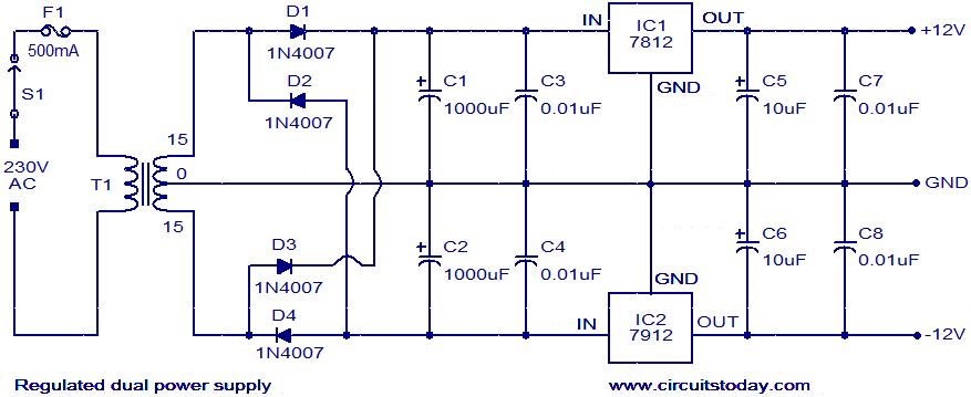
Your power supply is OK. If you are going to add a high pass filter to the system, you might want to consider better regulators.
What do you mean by more bass? Are you looking for deeper or louder? That chest thumping feeling is usually not very deep.
If you are just looking for louder, change your filter's R3 to a 100K or 250K pot, that will give you the ability to dial in more gain.
Your power supply is OK. If you are going to add a high pass filter to the system, you might want to consider better regulators.
What are your main speakers and subwoofer's rated sensitivity? (xx dB @2.83V)
... we need to know your mains' low end capability and how you are rolling them off.
I need your help to find a sub woofer ( car sub woofer ) with its box for my amp
as I said before my two mini sub are not from a well-known mark and I just could read there watts and there ohms
Now I want to buy a sub woofer with a proper box
Can you help me to buy an excellent sub for my amp ( for my computer's speaker )
but I want it to have a powerful voice a please don't consider that this sub is for home and doesn't need high power.
and by more bass, I meant more chest thumping feeling ( as you said )
Try increasing the crossover frequency to it's maximum (R5/7 to minimum) and turning up the gain (P3 set to it's maximum resistance) if you need more gain, and don't can't easily purchase a 100K or 250K pot, add a 39K resistor between R3 and the connection to R1 and R2. I assume that you had to buy more than two 39K resistors when you built the filter and have some on hand. If not, you can try 47K, or if that isn't enough 100K. This will make your 8" drivers play louder and hopefully have some overlap with the mains to get you some chest thump.
It's hard to recommend another driver without knowing your space constraints and budget. For small room/computer use, I'd normally say something like a 10-12" driver, maybe Peerless XXLS or similar. But since you're not really looking for deep bass almost any 12" driver that can go down to 60 Hz in a reasonable size enclosure should provide some thump. What drivers are available to you at reasonable cost?
What are your main speakers?
Kenwood and pioneer and Jbl are plentiful here
If you know a specific type from these marks I'll search and see If we have that one here
I planned to buy Kenwood C10 12" 200W Rms
I'll expend about 80 or even 90 dollars for just sub and about 30 or 40 dollars for the Box
my main speaker are weak now and I'm going to raise them to an acceptable main speaker.
but my only problem is to build my subwoofer system and match it with a good sub and box
you count highest possible amount for room area
I'm a JBL fan, using their 2245H (obsolete) pro woofers as subs. I don't know their car line, though. The Kenwood would probably work fine.
Do you have the thiele-small parameters for the drivers you are considering? If not you're going to be in build and guess territory unless you can measure them. A place to start would be to use something 20% bigger than their maximum recommended sealed box size. Try asking in the car audio forum for box recommendations for your chosen woofer in home use.
Weak mains are probably why you aren't feeling a thump. Crossing to a sub is usually below the thump region, so it's all on the mains. That's why I suggested maximizing the crossover frequency and turning the subs up. You might not have to buy anything new for the bottom and can upgrade your mains sooner.
Last edited:
That's the problem with car drivers - they don't often come with detailed specifications for scientific enclosure design. If they included response curves for their recommended enclosures, you could get some idea of the driver parameters.
Since your stated goal is Boomy, I'd go with something close to their recommended sealed volume, lightly stuffed. It it doesn't thump enough, add some blocks of wood inside the enclosure to reduce the volume. Too boomy, add some more stuffing or build a new box a bit bigger. Don't finish the box until you have determined that the box is an appropriate size.
How many output devices and how much heat sink does your amp have? If you skimped at all on either, it probably would be best to go with the DVC version and wire the voice coils in series to give you an 8 ohm driver. If you are sure that your amp can handle 4 ohm loads go with the single voice coil option.
Hi BobEllis
My ideal subwoofer for my home computer's speaker is this speaker from SONY
Can I use its filter for my amplifier and sub system?
this subwoofer is excellent and I always wanted to build it myself
Sony-SAWP16 actsub.pdf
http://rapidshare.com/files/450562736/Sony-SAWP16_actsub.pdf
My ideal subwoofer for my home computer's speaker is this speaker from SONY
Can I use its filter for my amplifier and sub system?
this subwoofer is excellent and I always wanted to build it myself
Sony-SAWP16 actsub.pdf
http://rapidshare.com/files/450562736/Sony-SAWP16_actsub.pdf
That sub doesn't have any low pass filtering, it was sold as part of an HT system where the receiver did the low pass filtering. Go ahead and use the filter you have, possibly modifying if you need more gain as outlined above.
I want to replace this filter because it has some noise on it
Is this because I used resister with 20% tolerances? or because I used 0.47uf for C5 and 0.22uf for C4 and I remove C1 from circuit ( open circuit )? and use 200 ohm resistor for R10?
I think the endurable voltage of these capacitor are low because they are very tiny
Is this because I used resister with 20% tolerances? or because I used 0.47uf for C5 and 0.22uf for C4 and I remove C1 from circuit ( open circuit )? and use 200 ohm resistor for R10?
I think the endurable voltage of these capacitor are low because they are very tiny
Noise meaning hiss or something with no signal or the way you described noise earlier, meaning that you could hear vocals in the subwoofer? Not having C1 could allow the circuit to oscillate which might sound like hiss. It could also be a characteristic of the opamp you used. Did you use a TL062 or something else?
Your using 20% parts probably has little impact, since you are using a variable resistor to set the frequency and your caps are probably 10% anyway. As long as the caps are in the same ratio, the shape of the response is about the same, it just impacts the maximum and minimum frequencies you can set. If you can, try to get R6 and R8 fairly close in value, but the absolute value doesn't really matter.
Download one of the free circuit simulators , such as LTSpice and play with the circuit values. If you have a DMM that will measure capacitance, you can determine the actual response.
You might try using a 4th order low pass filter as shown on the Linkwitz site I linked to. Use the mixer part of your circuit, connecting the 4th order filter where R6 connects to the circuit to the left. Use tight tolerance parts if possible. I use 1% metal film resistors and caps selected to at least 2%. Thinking that you will eventually lean towards accurate reproduction, select fixed parts to give you around an 80 Hz crossover frequency.
There is a calculator for Linkwitz-Riley crossovers available at Linkwitz-Riley Electronic Crossover, along with a circuit for a stereo crossover that many have used. Rod has boards available.
For this circuit, almost any film cap you find has suitable voltage capacity. The absolute worst case with your PSU is 24V. Low value film caps as you would likely use here are usually rated at 50-63V.
I used Electronic workbench V10 to simulate upper circuit but when I inject about 0.5 or 1 Vrms V(AC) ( with different frequency from 1 to 150 HZ or even higher ) and when I used the Oscilloscope to compare Input and out put signal, I saw that the out put signal in the pike of wave(sin wave) doesn't have curve shaped and they've rectangle shape with some wrinkle on them.
but when I simulate another filter (from Sony subwoofer) it was quite curve like input signal that you could increase the gain as you could reach about 2Vrms without any wrinkles.
In Sony circuit when I increased the frequency to about 250Hz the out put signal decreased to about 0V
Please don't laugh
I told you earlier that I'm not veteran
than forgive me If you heard some funny Ideas
I guess that I missed the part of the Sony circuit that provides a low pass.
Are you saying the simulation shows distortion or that you used a scope on the real thing? If the simulation, try reducing the value of R3 to 19K. It could be that the gain is too high causing the the mixer/buffer to clip.
Try simulating Rod Elliot's circuit using 12V power. He's set the crossover point at 300 Hz, but you can adjust values to make it 100 Hz using his calculator. He uses the same basic filter topology that you do with fixed resistors. It works great when properly implemented.
Again,
what do you mean by noise on the output?
What opamp did you use?
Can you measure the values of your resistors and caps?
By saying noise on the output, I meant a little ( more than a little ) buzz with singer voice and thumping.
I used Tl062 because of its low noise. and I tried 4558 to but when I use cell phone in my room ( 2 or even 3 meters away from my amplifier and filter box ) I could hear the Mobile signal on the sub (highly) but with TL072 I just hear that Mobile noise when I put the Mobile on the box of amplifier and filter.
I can measure the resistors but I don't know how to do it for caps???
- Status
- Not open for further replies.
- Home
- Source & Line
- Analog Line Level
- Subwoofer filter problem - Please help me