I'm referring to the heatsinks on Q3 and Q4 on the BA-3 front-end board: https://files.diyaudio.com/archive/gallery/data/500/IMG_04151.jpg
There are no mount points for a heatsink on the board. The heatsinks I selected don't sit flush on the board, and bend back and forth as I connect test probes and such. Can someone suggest a heatsink that will mount flush with the board, or otherwise make secure contact, so that it doesn't act as a hinge on the transistor legs?
There are no mount points for a heatsink on the board. The heatsinks I selected don't sit flush on the board, and bend back and forth as I connect test probes and such. Can someone suggest a heatsink that will mount flush with the board, or otherwise make secure contact, so that it doesn't act as a hinge on the transistor legs?
Attachments


Just drill another hole in the sink after measuring.
Or remove transistors from PCB, cut their legs to size, put them back.
First see the circuit works.
Or remove transistors from PCB, cut their legs to size, put them back.
First see the circuit works.
1) Drill a new hole/cut legs somewhat shorter/both so bottom edge of heat sink sits against PCB surface.
2) *glue* heatsink to PCB.
You need a somewhat elastic adhesive (no Krazy Glue, no Epoxy, no hot glue gun, etc.) because PCB surface is hard and not porous, heatsink metal same thing, and any impact will make them separate, because PCB will flex a little; a somewhat elastic adhesive will "follow" that flexing.
Recommended: thickish rubber contact cement, the kind designed for shoe soles and such
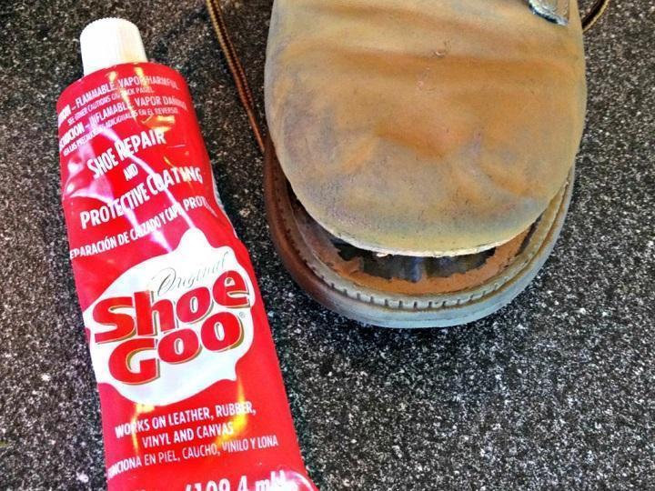
or silicone sealant, the kind used to seal windows against rain, kitchen countertops, fish tanks, etc.

After a week or so they will be almost impossible to remove, go figure.
Apply a bead along heatsink edge, touch PCB with it so you transfer some, apply extra adhesive again to heat sink edge, mount it on PCB, now bolting transistor down, and let it dry.
When/if you need to remove that transistor, unscrew and unsolder it , heatsink will stay permanently bonded to PCB.
I do that all the time; I have machines to cut/punch/bend my aluminum chassis in house, so always have random aluminum strip leftovers lying around, perfect for simple heatsinks, which get glued to PCBs.
2) *glue* heatsink to PCB.
You need a somewhat elastic adhesive (no Krazy Glue, no Epoxy, no hot glue gun, etc.) because PCB surface is hard and not porous, heatsink metal same thing, and any impact will make them separate, because PCB will flex a little; a somewhat elastic adhesive will "follow" that flexing.
Recommended: thickish rubber contact cement, the kind designed for shoe soles and such
or silicone sealant, the kind used to seal windows against rain, kitchen countertops, fish tanks, etc.
After a week or so they will be almost impossible to remove, go figure.
Apply a bead along heatsink edge, touch PCB with it so you transfer some, apply extra adhesive again to heat sink edge, mount it on PCB, now bolting transistor down, and let it dry.
When/if you need to remove that transistor, unscrew and unsolder it , heatsink will stay permanently bonded to PCB.
I do that all the time; I have machines to cut/punch/bend my aluminum chassis in house, so always have random aluminum strip leftovers lying around, perfect for simple heatsinks, which get glued to PCBs.
Last edited:
I'm referring to the heatsinks on Q3 and Q4 on the BA-3 front-end board: https://files.diyaudio.com/archive/gallery/data/500/IMG_04151.jpg
There are no mount points for a heat sink on the board. The heat sinks I selected don't sit flush on the board, and bend back and forth as I connect test probes and such. Can someone suggest a heat sink that will mount flush with the board, or otherwise make secure contact, so that it doesn't act as a hinge on the transistor legs?
I think the fault is on your side.
1. In the pic where the board is shown, the resistors R10 are lifted up from PCB, same for R11. So you can bend them back a little bit, so sinks will fit if you do not have the sinks for which the board was designed in first place.
2. Then also Heat sink will fit. The Mount points are the white lines drawn on the board.
3. the Capacitor C1 & C2 seems to be oversize, because in your picture, the CAP don't fit in the space designed for it..
4. the use that Glue as JM_Fahey suggested, don't use too much it will be stress if you have to remove it at a later day..
5. last but not least I think that way from looking at your pics and the original board the heat sinks will just fit beautiful
Also I see you need to improve your soldering techniques, start with to use less solder and all will come to a nice end.
The main issue with the heat sinks I selected is that when screwed to the transistors, they don’t sit flush on the board even with the transistors fully inserted into the holes (as they are in my photos). I suppose I could drill new holes. But I’d prefer to buy a heat sink that will fit flush by default.
Do you know what heat sinks the board was designed for? That’s never mentioned anywhere.
Do you know what heat sinks the board was designed for? That’s never mentioned anywhere.
Heat sinks are sold for device package and dissipation capacity.
Not for PCB size.
You are in the wrong aisle, so to speak.
Not for PCB size.
You are in the wrong aisle, so to speak.
I did shop based on package size and thermal capability. On Mouser, and all the other sites I’ve checked, heat sinks are rated by “thermal resistance”. The datasheet for the transistors lists “thermal dissipation”. How do you convert between the two ratings?
You bought a PCB from the DIYA Store.
You can best ask them at their helpdesk :
Burning Amplifiers
Patrick
You can best ask them at their helpdesk :
Burning Amplifiers
Patrick
They designed the thing; they sold you the boards.
So they should give you a good answer.
Patrick
So they should give you a good answer.
Patrick
To your first post: Yes, he did. It’s in his original article for the BA-3.
To your second post: I did.
To your second post: I did.
- Home
- Design & Build
- Construction Tips
- Suggestions for MOSFET heatsinks that will most securely against PCB?