 Hi,
Hi,After a couple of Sony TC-500A tear downs I have recycled the Tamradio Tamura Nickel Output transformers and Sony Holey Basket FE103A Alnico speakers .
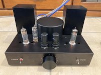
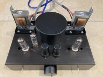
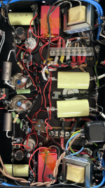
The Configuration consists of a 6J5 driver tube and Single Ended EL84 output tube running in Pentode mode 5 watts output.
The Cathode of the EL84 is set to 40mA with a LM317 regulator and a 22v Zenner Diode to set the Control Grid Voltage .
A EZ81 rectifier tube using a low noise Toroidal Power Transformer .
Power Supply Capacitors are all Film
Other parts are Dale Wire Wound , Kiwame Carbon , Caddock thick film Resistors and Russian K40Y signal capacitors .
Hook up wire is mainly Kimber Teflon OFC Copper .
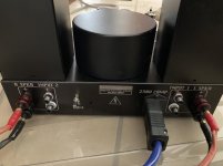
Input RCA and Speaker Terminals KLE Low Mass Copper .
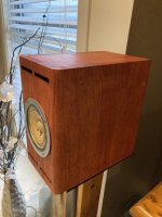
The Sony Holey Baskets- Fostex FE103A / Alnico speakers are housed in a copy of the Humble HiFi Solo 103 cabinets, http://www.humblehomemadehifi.com/download/Humble Homemade Hifi_Solo-103.pdf
The System has excellent resolution and a very natural sound, Vocals have a real lifelike quality as do musical instruments , probably due to the Tamradio Vintage Permalloy Output transformers and high quality parts.
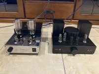
I prefer this amp to the Audion 300B for naturalness of human voice also pictured here .
Lower bass frequencies can't be expected without a sub woofer .
The Chassis is from Hammond as are the DC chokes which are dual rail past the first two smoothing capacitors .
In summary a great sounding second system from recycled parts .
Attachments
Last edited:
Does your amplifier have global negative feedback?
The coupling capacitor coming from the 6J5 is connected to a 470K gridleak resistor and to an other part that is in the lead to the control grid of the EL84. Is that a non-inductive resistor (gridstopper)?
Could you show us the schematic of your amplifier?
The coupling capacitor coming from the 6J5 is connected to a 470K gridleak resistor and to an other part that is in the lead to the control grid of the EL84. Is that a non-inductive resistor (gridstopper)?
Could you show us the schematic of your amplifier?
The gridstopped is a KOA Speer from Mouser Carbon Film .
Great value for money .
When i get some time off I'll draw up the schematic , its pretty simple really being Single Ended .
Great value for money .
When i get some time off I'll draw up the schematic , its pretty simple really being Single Ended .
The global feedback is necessary if you want decent bass .
You can experiment between 4.7K-18K
I prefer the 6J5 or you could use a single 6SN7 , to a ECC81 which is to steely and bright for my taste.
You can experiment between 4.7K-18K
I prefer the 6J5 or you could use a single 6SN7 , to a ECC81 which is to steely and bright for my taste.
Last edited:
I searched the Mouser website using "KOA Speer carbon film" but that gives too many results (4506 items found). Could you please be a bit more specific?
The feedback is very hard to make out on the picture. I see the twisted red and black wires for feeding the filament of the 6J5. But I can't detect a third wire for feedback going to the cathode resistors of a 6J5 (there have to be two resistors because an electrolytic capacitor seems to be bypassing one of them).
The feedback is very hard to make out on the picture. I see the twisted red and black wires for feeding the filament of the 6J5. But I can't detect a third wire for feedback going to the cathode resistors of a 6J5 (there have to be two resistors because an electrolytic capacitor seems to be bypassing one of them).
Last edited:
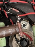
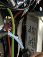
You will see a mid point in the two Cathode R for the 6J5 that feed off to the feedback resistor in the heat shrink just before the + Spkr terminal .
Will likely put a piece of small tag strip off one lug of the DC choke so different CFB resistors can be applied .
Trying to reverse engineer a schematic can be difficult from images alone .
The El84 output is similar to the RH84 but used a 28 ohm resistor to set the CCS current and a 22V zenner on the control grid .
RH Amplifiers: RH84 amplifier - revision 2
I don't like the bright sounding ECC81 tubes and much prefer a 6J5 or a single 6SN7 = one triode each channel , as the curves are so linear and the PR much lower than a 12AT7 ( ecc81 ) so the drive impedance seen by the El84 grid is much lower. ,
The 6J5 is a simple RC setup with a 30k 5 watt Kiwame plate resistor and a Dale Metal film and TAKMAN carbon cathode resistors, the CFB resistor is also a TAKMAN carbon.
The schematic is simple the results are very pleasing , no point in over engineering a simple single ended EL84 .
The Power supply Toroidal from Antek is very quiet allowing a small chassis without hum .
The first pair of parallel 20uF 400V smoothing capacitors are CDE/PHC from mouser, they last unto 100000 hours VDC and better than the stuff sold on DIY supply sites for this purpose, excellent at tackling residual AC ripple after the EZ81.
The two AC drop resistors in series are 3watt Dale wire wound 150 ohm to protect the EZ81 from the initial inrush current,
https://www.mouser.com/ProductDetai...tor/156PHC600KS?qs=3tP%2BN51vMXcQ1u3pSEMarA==
Last edited by a moderator:
OK, thanks. Than the GNFB was installed at a later moment because the picture in post #1 doesn't show it yet. There the negative lead of the electrolytic capacitor still shared a ground point with the 470K grid resistor of the EL84.
I'm still curious about the type of grid stoppers being used.
I'm still curious about the type of grid stoppers being used.
https://au.mouser.com/datasheet/2/219/SPR-12666.pdf
The Larger wattage versions seem identical to Kiwame in appearance
The Larger wattage versions seem identical to Kiwame in appearance
Caddock 300 ohm
These are directly in the signal path, are typically Non Inductive and very clean sounding
https://au.mouser.com/ProductDetail...GAEpiMZZMtlubZbdhIBIEP7%2BjuVG1rhBsfQzFJKtA4=
These are directly in the signal path, are typically Non Inductive and very clean sounding
https://au.mouser.com/ProductDetail...GAEpiMZZMtlubZbdhIBIEP7%2BjuVG1rhBsfQzFJKtA4=
As this amp is a work in progress , I have experimented with KAO and Kiwame.
The 30K 5 watt Carbon Kiwame on the plate of the 6J5v is very important to the sonics of the amplifier , 470 ohm total on the cathode has a Dale Metal film and a Takman carbon as the combined values needed are harder to find .
I have found the sound of the first tube in a single ended amp , has the greatest effect on the sonic quality of the finished design .
Get the best output transformer you can afford and a quiet toroidal power transformer and you are %90 there .
Circuit design obviously sets the operating perimeters , even if you use KOA resistors everywhere and Russian K-40y coupling capacitors your fished product is likely to sound better than most shop sold tube amps costing many thousands of dollars .
The SE EL84 pictured next to the Audion is a classic example to me , a well respected SE 300B amp next to a DIY SE EL84 admittedly with Vintage Tamradio iron IHMO is much more musical to my ears and a fraction of the price .
Cathode By-Pass is a Elna Silmic II
Elna Capacitor 100uF 35Vdc RFS
Last edited:
Since your amplifier is a work in progress and since there is a lot of modding going on (on your picture in post #7 there still is a Mills resistor in the cathode lead of the 6J5), you might consider soldering the grid stoppers of the EL84's closer to the tube base. The lead of the grid stopper connected to the tube base should be as short as possible in order to do its job right.
What are the cathode and anode voltages of the 6J5?
What are the cathode and anode voltages of the 6J5?
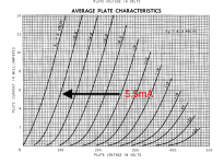 Hi,
Hi,Here is the chosen operating point, with Ohms Law you will be able to work out the voltage across the 30K /5 watt Plate R .
The Cathode R needs to total between 430- 470 ohms depends on bias @ - 2.3V
Remember the CFB needs to be taken after the first resistor and the junction of final resistor to ground .
Last edited:
The 300 ohm Caddock Grid Stopper is Non Inductive and is not effected by
high frequency parasitic oscillation , RF freq interface and can help limit grid current when the tube is driven into the positive grid region and can help in preventing "blocking" distortion.
Yes it is good practice to solder it direct to the tube grid input socket but in this case does not cause any issues .
Tubes like E180F , E280F and especially D3A really need a grid stoppers and ceramic beads very close to the tube solder lug to prevent runaway occilation as they are HF tubes and 6J5 is not .
Why grid stoppers with a 30 Watt rating? And why/when would you drive the EL84's into the grid current region? And if so, what difference would 300 Ohm than make?
The 6J5 is probably not so prone to oscillate. But in your amplifier the grid stoppers for the 6J5 are soldered straight onto the tube socket anyway. But the grid stoppers at the tube socktes of the EL84's are not. The EL84 is a pretty steep tube so I advise you (again) to solder those grid stoppers straight to the tube socket. To write that this good practice while not following that practice seems weird to me.
In post #12 you wrote that these grid stoppers are very clean sounding. Normally I don' comment on others writing about how something sound. But being able to hear how a certain brand/type of grid stopper of 300 Ohm sounds, seems completely over the top to me. I just can't believe that someone would be able to hear that.
Anything directly in the signal path will influence the sound of an amplifier , hence using the best component possible that is non inductive is very important .
It is best DIY's try it for themselves and can make up their own minds.
To get a 30 watt rating a heat sink is needed as this resistor can be used for many purposes.
They are excellent and wind up in very expensive products.
Believing is hearing !
One of the purposes of this post was for DIY's to use a 6SN7/ 6J5 as a drive tube for a SE EL84 rather than a ECC81/12AT7, and see if they prefer it.
To experiment with different components and recycled old Sony tape machine output transformers.
Permalloy is IMHO the king of the pile for metal for output transformers . I have tried M6,M3, Finemet, Amorphous and M19 steel so again its a chance for DIY's to pick up cheap Nickel iron as I believe it to be and experiment .
It is best now for others to comment if they choose .
Last edited:
Forgot to mention the Sony Tamradio/Tamura output transformer also works well with a type 45 output tube being 5K primary , and 8 ohm/600ohm output also suitable for a headphone amp.
Bass is rolled of at 39Hz -1dB being rather small and Nickel saturating more easily than Silicon Steel .
Bass is rolled of at 39Hz -1dB being rather small and Nickel saturating more easily than Silicon Steel .
- Home
- Amplifiers
- Tubes / Valves
- Tamradio Tamura Sony TC-500A Recycled Transformers

