This may not answer your question, but your attached document is from Martin King whose TL- modeling software is what I've used for years with very good results. You have or will read some places that a specific ratio of So/Sd is necessary and that is simply not true. What you do is set up a model with the starting width of the line a bit larger than the outer flange diameter of the driver. You should estimate what the optimum 1/4-wavelength resonant frequency needs to be, which is the sole tuning mechanism, then make the line's length and taper ratio as necessary to achieve that goal. You then increase the line's width in order to increase the line's volume so that your desired bass response reach is obtained. You can also increase the line's depth while maintaining its width and taper ratio. Start out with a taper ratio of at least 8:1 (decreasing area from beginning to end of the line). This will provide immense help in minimizing ripples in the shape of the overall response curve. I've never used a taper ratio less than 10:1 and have used one as large as 25:1 with good results. A tapered line is always shorter than a non-tapered line because its quarter-wave resonant frequency is based on its effective length, which is longer than it actual length, while the line's volume is the final determiner of its bass reach.
Paul
Paul
Thanks for info. Now is clear. I will start with 5:1 ratio. What is your experiance with damping line?
For a tapered line I place polyester fiber (don't bother with long-fiber wool) in about the first 2/3 of the line's length and usually with a density of 0.75 lb/ft3, but sometimes up to 1 lb/ft3. With a taper ratio of 5:1 the line will need to be about 71% of the length of an equivalent non-tapered line. If you tell me what your driver's Qts and Fs are, I should be able to estimate reasonably accurately how long your line needs to be with a 5:1 taper.
Paul
Paul
https://sbacoustics.com/product/6½in-satori-mw16pnw-4/
My calaculation 5:1, length cca 2-2.1 meter, volume 22 liter, SO 180 cm2, SL 36 cm2. Is it ok my calaculation
My calaculation 5:1, length cca 2-2.1 meter, volume 22 liter, SO 180 cm2, SL 36 cm2. Is it ok my calaculation
Your line would end up having a 1/4-wave resonance of about 31 Hz. If your driver had a Qts equal or close to 0.40, that would likely be a good result, but your driver has a Qts of 0.27 which will require a tuning frequency (the line's 1/4-wave resonance) considerably higher than its Fs of 28 Hz, possibly approaching 40 Hz. So, in general, when Qts is lower than 0.40, the optimum tuning frequency will be higher than Fs, and when Qts is higher than 0.40, the optimum tuning frequency will be lower than Fs. Also, in my experience drivers with a Qts below 0.30 have not performed at all well in a TL, and will likely work better in a ported box or at best, in an ML-TL with a rather short length (your proposed line length is just too long having an effective length of 2.8 meters). If you give me a bit more time I will do a quick model of what you've proposed based on the driver's published T/S values and share the results.https://sbacoustics.com/product/6½in-satori-mw16pnw-4/
My calaculation 5:1, length cca 2-2.1 meter, volume 22 liter, SO 180 cm2, SL 36 cm2. Is it ok my calaculation
Paul

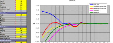
Done. I've attached my modeling results. There are two graphs, the first showing what your results would be due to the too-low tuning frequency, and the second after I shortened the line to raise its tuning frequency, while keeping the same starting and ending areas you used. While the second modeling results in a rather high f3, that would be improved simply by increasing both So and Sl while keeping the same tuning frequency.
Paul
Paul
Attachments
Do note that (other than Martin using it as a dimension unit) has nothing directly to do with the start or end cross-sections.
A heavily tapered line can be shorter and i know Paul likes 10:1. I use that in my midTLs.
But MJK’s software has opened up a huge new accesible design space, and designers tend to have preferences (scottmoose likes ML-TLs, Pail heavily tapered more convential TLs).
dave
A heavily tapered line can be shorter and i know Paul likes 10:1. I use that in my midTLs.
But MJK’s software has opened up a huge new accesible design space, and designers tend to have preferences (scottmoose likes ML-TLs, Pail heavily tapered more convential TLs).
dave
Dave, most recently (see attachment) I built a pair of speakers with a 14:1 tapered and mass-loaded line, the Duetta, which won first place in the under-$300 category at the recent Parts Express Speaker Design Competition (formerly MWAF). And, I've built more ML-TLs for personal use than tapered ones. Just goes to prove how versatile Martin's software is.Do note that (other than Martin using it as a dimension unit) has nothing directly to do with the start or end cross-sections.
A heavily tapered line can be shorter and i know Paul likes 10:1. I use that in my midTLs.
But MJK’s software has opened up a huge new accesible design space, and designers tend to have preferences (scottmoose likes ML-TLs, Pail heavily tapered more convential TLs).
dave
Paul
Attachments
Last edited:
Paul thanks for sharing experience with TL and congratulation on project with Dayton drivers. I have plan to use first electrical order crossover on Satori woofer so Qts will be around 0.31. Regarding ML TL you think it is better to put Satori with low Qts. Something like Tabaq design or accidental MLTL box.
You attached calculation and SPL graph is with out room gain. Maybe 2m (it is 2.77m when put tapered ratio 5:1) physical's length is way to go with net volume around 20 liter. See attached file with room gain, fb=28
You attached calculation and SPL graph is with out room gain. Maybe 2m (it is 2.77m when put tapered ratio 5:1) physical's length is way to go with net volume around 20 liter. See attached file with room gain, fb=28
Attachments
Last edited:
I have plan to use first electrical order crossover on Satori woofer so Qts will be around 0.31
What does the XO have to do with the Q?
A Q of 0.31 (for a driver in a box) is very low, and the term only applies to a sealed box.
dave
When you put coil on woofer (low pass) it will increase Qts, coil have cca 0,3 ohmWhat does the XO have to do with the Q?
A Q of 0.31 (for a driver in a box) is very low, and the term only applies to a sealed box.
dave
Pkitt assisted me in designing a 12:1 TL for a seas W22EX. Unfortunately a wrong cut with my router damped my enthusiasm for the project, but before ruining one of my boxes the listening test seemed to verify the calculations with a high quality "deep, dry quality" bass.
However I made one observation: Using a tuned length = element Fs have a limited SPL before reaching max excursion with associated "huffing and puffing", particularly round the phase-plug.
Given this, the conclusion from the pdf is a positive surprise to me:
"......Equivalent bass reflex and transmission line enclosures have equal internal air volumes Vb and tuning frequencies fb....."
Can this be interpreted as "given the same tuning and box volume the excursion requirements will be the same"
Are there any rules of thumb for recommended tuning frequency vs. Sd or Vas?
Yes, room gain is not accounted for, but may not amount to much, but baffle step losses aren't accounted for either which will offset room gain most likely. Keep in mind that most, if not all, modeling software for however the box may be configured, is "ideal".Paul thanks for sharing experience with TL and congratulation on project with Dayton drivers. I have plan to use first electrical order crossover on Satori woofer so Qts will be around 0.31. Regarding ML TL you think it is better to put Satori with low Qts. Something like Tabaq design or accidental MLTL box.
You attached calculation and SPL graph is with out room gain. Maybe 2m (it is 2.77m when put tapered ratio 5:1) physical's length is way to go with net volume around 20 liter. See attached file with room gain, fb=28
TLs, bass reflex and ported boxes all are inherently 4th-order designs, although their roll-offs below the knee in the bass response curves don't necessarily have to be 4th-order, and can be made to have a 3rd-order or a bit less depending on the design. Whatever the box design is, you have to pay attention to both driver excursion and port or terminus air flow velocity and make the necessary changes and compromises to achieve your desired goals if possible. I always determine how much input power is required to cause the driver excursion to reach Xmax+15%, then note what the peak air velocity is. If that velocity is not more than 17 m/s and the driver is generating adequate SPL, then the design is good to go. If not, I'll make changes to the design. I've never had any of my personal tapered or mass-loaded TLs exhibit huffing and puffing.Pkitt assisted me in designing a 12:1 TL for a seas W22EX. Unfortunately a wrong cut with my router damped my enthusiasm for the project, but before ruining one of my boxes the listening test seemed to verify the calculations with a high quality "deep, dry quality" bass.
However I made one observation: Using a tuned length = element Fs have a limited SPL before reaching max excursion with associated "huffing and puffing", particularly round the phase-plug.
Given this, the conclusion from the pdf is a positive surprise to me:
"......Equivalent bass reflex and transmission line enclosures have equal internal air volumes Vb and tuning frequencies fb....."
Can this be interpreted as "given the same tuning and box volume the excursion requirements will be the same"
Are there any rules of thumb for recommended tuning frequency vs. Sd or Vas?
Paul
What are you trying to achieve in bass reach and SPL output with this SB driver?Paul thanks for sharing experience with TL and congratulation on project with Dayton drivers. I have plan to use first electrical order crossover on Satori woofer so Qts will be around 0.31. Regarding ML TL you think it is better to put Satori with low Qts. Something like Tabaq design or accidental MLTL box.
You attached calculation and SPL graph is with out room gain. Maybe 2m (it is 2.77m when put tapered ratio 5:1) physical's length is way to go with net volume around 20 liter. See attached file with room gain, fb=28
In case it was not clear, it is not the TL design per see or the terminus airflow causing wind-noise. It was the sealing (or lack thereof) and the tight tolerances around the copper phase plug causing it. That said; I was listening to a single speaker in the center of a large room. In a smaller room, in stereo and a somewhat closer to walls the speakers will likely have full benefit of the low frequency response with sufficient SPL without unwanted noise.............. I've never had any of my personal tapered or mass-loaded TLs exhibit huffing and puffing........
Paul
I need good bass response from 35 Hz in two way speakers balance sound from bass to treble. I will pair Satori woofer first with my friend Raven ribbon for test propose and next step I will try this tweeter with simple first order electrical crossover.What are you trying to achieve in bass reach and SPL output with this SB driver?
https://www.morelhifi.com/wp-content/uploads/2020/01/CAT378.pdf
- Home
- Loudspeakers
- Multi-Way
- Tapered transmission line So/Sd ratio