Good Day. I am currently repairing a Taramps Bass1200 that came in powering up but with no audio. It was not in protect mode but there was 4.3v across the speaker terminals.
When checked, both outputs (IRFB4115) were testing as good but the 4R7 resistor at R60 was burnt open. I replaced that and then the amplifier would start and shut down repeatedly. The IRS2092S is likely damaged as it reads 192ohms between COM and LO out of the board. I have a brand new replacement but I want to make sure there isn't an errant voltage present that will damage it as soon as I put it in as these are hard to find. Below are the voltages on the pads for the IRS2092:
1: 5.2v VAA
2: 18mv GND
3: 18mv IN-
4: 2mv COMP
5: -4.8v CSD
6: -5.2v VSS
7: -3mv VREF
8: -49.5v OCSET
9: -55.9v DT
10: -55.8v COM
11: -55.6v LO
12: -43.4v VCC
13: 24mv VS
14: 24mv HO
15: 39.4v VB
16: 24mv CSH
Attachments


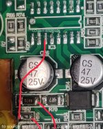
One side of R60 is directly connected to the gate leg (leg1) of output FET2 (IRFB4115) and the other end of R60 is directly connected to pin11 (LO) of IRS2092s. The end connected to pin11 is connected to R65 (10k resistor) and then output FET2 (IRFB4115) source leg (leg3).
Attachments
Are you sure that the outputs checked to be OK?
R60 appears to be the gate resistor.
What's the resistance across the gate and source legs of the output transistors?
R60 appears to be the gate resistor.
What's the resistance across the gate and source legs of the output transistors?
Resistance across the high side output is 6.8k and across the low side output, 10k. I removed the outputs and checked them and they checked good in comparison to a known good output I had. The outputs were not damaged in this amp, just R60 was open and there was no output, and likely a damaged IRS2092s.
The resistors don't generally burn for no reason.
As far as I know, the only things that could cause the resistor to open is a defective G-S Zener or a defective output transistor... and, maybe as a long-shot, a stray strand of wire that got into the amp.
As far as I know, the only things that could cause the resistor to open is a defective G-S Zener or a defective output transistor... and, maybe as a long-shot, a stray strand of wire that got into the amp.
There were wire strands inside the amp. I suspect that was the cause of the damage as I experienced similar failures with Timpano and Stetsom amplifiers.
The outputs test good, I am just hoping to get confirmation that there are no obviously dangerous readings on the pads of the IRS2092s that would cause sure failure. If failure occurs because of some other part of the amp that is not exposing itself currently, that's fine. I just thought I would ask for a second opinion before just sticking in the new IC because I am not fully verse with the pins and their functions...
The outputs test good, I am just hoping to get confirmation that there are no obviously dangerous readings on the pads of the IRS2092s that would cause sure failure. If failure occurs because of some other part of the amp that is not exposing itself currently, that's fine. I just thought I would ask for a second opinion before just sticking in the new IC because I am not fully verse with the pins and their functions...
I don't see a problem with the voltages posted but I wanted to know more before I said so because it looked like there could have been another problem.
Before installing the IC is there a way to check it with a meter to see if it is good/genuine? Something similar to the checks that can be performed on the IR21844. I got the IC from a local supplier and have used one before on a Stetsom 800.4 which is still working properly to this day but I just would like to cover both ends before installing... The defective one that came out is reading 192ohms between LO and COM while the new one reads 2megaohms... Are there any resistance readings between legs that should indicate a good IC?
I think you'd have to have a genuine IC to know what you should read for some terminals.
For the high and low-side sections, you confirm that the output terminal isn't shorted or leaking to the high or low supply pins for each one. Like you found with the damaged IC, when an output section is damaged, it often shorts (leaks) to one of the supply pins.
Another thing you do when there are multiple ICs is to confirm that the readings from one IC to another to confirm that they're about the same. I've had some fail when installing them and some terminals read significantly different between corresponding terminals.
I'm not familiar with this IC but you may be able to get it to produce output pulses without the FETs in the amp if you connect the OCSET terminal to the vref terminal.
Using a low-voltage rail supply is another option. It helps protect the outputs which helps protect the IC.
Installed the new IC and the amplifier has clean output when tested on the bench. Will test it in a vehicle tomorrow but it appears to be repaired. I am more confident that the supplier's ICs are good so I may buy a few depending on his stock. Thanks for the assist.
- Home
- General Interest
- Car Audio
- Taramps Bass1200 IRS2092S replacement