I have weird problem. I am restoring an old sony reel to reel. I can remove the front, and work on belts and mechanical stuff, but i need to open the back and work on electronics too.
Problem is, i can't get the back cover off. This is embarrasing, but it seems like noone has ever removed the cover. I took the screws of, but there seems to be cover nailed to the wooden frame together. It looks like u shaped nails. Does not seem like easy way in.
Anybody has any experience with this? I thought removing back cover would be normal part of service.

I have experience with TC-377 and TC-645, but neither of them had the back cover stapled to the wooden frame. The cover is usually fixed by the screws that hold the rubber feet. I think someone has serviced it and believed that would be the last service ever.I have weird problem. I am restoring an old sony reel to reel. I can remove the front, and work on belts and mechanical stuff, but i need to open the back and work on electronics too.
Problem is, i can't get the back cover off. This is embarrasing, but it seems like noone has ever removed the cover. I took the screws of, but there seems to be cover nailed to the wooden frame together. It looks like u shaped nails. Does not seem like easy way in.
Anybody has any experience with this? I thought removing back cover would be normal part of service.
Here is a copy of the disassembly instructions. Hope it helps.
Thanks, that definitely helps.
In the mean time i downloaded full service manual.
It looks from the picture, if i understand correctly, one needs to remove the front cover completely, the back screws, leg screws, bunch of other screws on inside sides, and remove all the guts out. That seems only way to aproach boards with electronic.
Oh well, i gotta do it. I need to replace all signal caps and deoxit bunch of contacts.
I ordered complete belts kit too...
Wish me luck. Definitely not the frendliest beast to work on. Especialy some belts to be replaced...one need to take whole heads assembly out. I have seen videos for 377, look similar in construction.
Ok, there will be no rush on this restoration, i want to do it right.
Thanks again.
They are well made and give many years of quality use.
Follow the numbers in sequence. You can't go wrong.
Have fun
Follow the numbers in sequence. You can't go wrong.
Have fun
Ok, I am in!
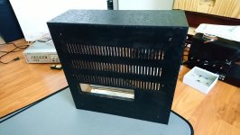
Well, as expected, I was right, the back cover is not removable, those nails were original by sony (which i painstakingly removed in hope to get back cover off). Anyway, here are some progress pictures. Just for laughs.
Well, as expected, I was right, the back cover is not removable, those nails were original by sony (which i painstakingly removed in hope to get back cover off). Anyway, here are some progress pictures. Just for laughs.
Attachments


Some progress...i replaced six capacitors in signal path, three per channel, two 10uF and one 6.8uF. I remeasured replaced cap, just out of curiosity.
Those four 10uF measure around 13uF each, 1.7 esr, 1.1% volt loss, not sure what that means.
Two 6.8uF caps look like tantalums, the measure 6.4 and 6.3 uF, 1.38 ohm esr, 0.3% volt loss.
I installed temporary belts and it is playing, sounds cleaner then before recaping. There is slight channel disbalance, not big.
Painting the wooden frame now. I do not like the look of fake wood, it will be my signature bubly black.
Still long way to go, but slowly getting there.
some more progress...
one VU meter light, right, was not working, light bulb gone, so I put two yellow leds in series with normal diode, since it powered by 6 volts ac. Well, they do not look exactly alike, but I will eventually do the same thing to the left channel. Once I receive the belts.
Channel imbalance is improving, I guess it just needs to be played.
Attachments


Adason…great post(s). Would you mind sharing which caps you replaced? I too had a tc399….many thx!some more progress...
one VU meter light, right, was not working, light bulb gone, so I put two yellow leds in series with normal diode, since it powered by 6 volts ac. Well, they do not look exactly alike, but I will eventually do the same thing to the left channel. Once I receive the belts.
Channel imbalance is improving, I guess it just needs to be played.
i replaced six capacitors in signal path, three per channel, two 10uF and one 6.8uF. I remeasured replaced cap, just out of curiosity.
Those four 10uF measure around 13uF each, 1.7 esr, 1.1% volt loss, not sure what that means.
Two 6.8uF caps look like tantalums, the measure 6.4 and 6.3 uF, 1.38 ohm esr, 0.3% volt loss.
Those four 10uF measure around 13uF each, 1.7 esr, 1.1% volt loss, not sure what that means.
Two 6.8uF caps look like tantalums, the measure 6.4 and 6.3 uF, 1.38 ohm esr, 0.3% volt loss.
Adason...thanks so much for your reply...I sincerely appreciate your help...RPi replaced six capacitors in signal path, three per channel, two 10uF and one 6.8uF. I remeasured replaced cap, just out of curiosity.
Those four 10uF measure around 13uF each, 1.7 esr, 1.1% volt loss, not sure what that means.
Two 6.8uF caps look like tantalums, the measure 6.4 and 6.3 uF, 1.38 ohm esr, 0.3% volt loss.
I believe i purchased service manual on cd, if you need schematics i can scan it and post.
Its very simple circuitry.
Its very simple circuitry.
Adason…thx again. I think I have the manual. My issue may be finding/locating these six caps on the 399 circuit board then sourcing and purchasing the correct caps. I’ve got good solder skills. But I’ve never messed w a factory circuit board. Where do you go to purchase capacitors? Many Thx !!!! Robert in Florida
- Home
- Source & Line
- Analogue Source
- TC-399 RTR, how to get in?