DNL = Differential Nonlinearity, best explained here:
https://www.mvaudiolabs.com/digital/tda1541a-dynamic-element-matching-slowed-down/
Especially interesting is the TDA1541 DAC conceptual schematics.
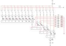
It is possible to influence the upper bit currents by adding or subtracting a small amount of "leakage" current of the DEM filter capacitors.
If a bit current deviates from the ideal, it causes DNL. The TDA1541A is specified for < 1 LSB DNL. Since the LSB is 61 nA, about half of this is the maximum current we have to inject at the DEM decoupling pins in or out. This tiny current can be generated by a 3 V source and a 10 MΩ resistor at each pins. The voltage is related to the default voltages at the DEM pins (that you can't measure with a DMM of 10 MΩ input resistance BTW bacause it causes a "leakage" current).
Previous work:
https://www.diyaudio.com/community/threads/dac-linearity-test-cd.113620/
https://www.diyaudio.com/community/threads/static-measurement-of-dac-linearity-possible.406689/
https://www.diyaudio.com/community/threads/16-bit-dac-at-60db.406935/page-5#post-7712941
Differential nonlinearity is the deviation when the bit current step is not exactly equal to with 1 LSB. Examples:
0000 0000 0000 0000 -> 0000 0000 0000 0001
0000 0000 0000 0001 -> 0000 0000 0000 0010 <- here 1 LSB change at bit #1
0000 0000 0000 0010 -> 0000 0000 0000 0011
etc.
Here and in the following I count the bits as LSB = bit #0, MSB = bit #15.
We are interested in the bit transitions of the upper 7 or 6 bits (more on it later), that is:
0111 1111 1111 1111 -> 1000 0000 0000 0000 (MSB, bit #15)
0011 1111 1111 1111 -> 0100 0000 0000 0000 (bit #14)
0001 1111 1111 1111 -> 0010 0000 0000 0000 (bit #13)
0000 1111 1111 1111 -> 0001 0000 0000 0000 (bit #12)
0000 0111 1111 1111 -> 0000 1000 0000 0000 (bit #11)
0000 0011 1111 1111 -> 0000 0100 0000 0000 (bit #10)
0000 0001 1111 1111 -> 0000 0010 0000 0000 (bit #9) - we will not use any correction here
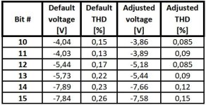
Now we just need to measure the THD around each bit transition, and inject a correction current in the DEM pins for reducing the THD.
https://www.mvaudiolabs.com/digital/tda1541a-dynamic-element-matching-slowed-down/
Especially interesting is the TDA1541 DAC conceptual schematics.
It is possible to influence the upper bit currents by adding or subtracting a small amount of "leakage" current of the DEM filter capacitors.
If a bit current deviates from the ideal, it causes DNL. The TDA1541A is specified for < 1 LSB DNL. Since the LSB is 61 nA, about half of this is the maximum current we have to inject at the DEM decoupling pins in or out. This tiny current can be generated by a 3 V source and a 10 MΩ resistor at each pins. The voltage is related to the default voltages at the DEM pins (that you can't measure with a DMM of 10 MΩ input resistance BTW bacause it causes a "leakage" current).
Previous work:
https://www.diyaudio.com/community/threads/dac-linearity-test-cd.113620/
https://www.diyaudio.com/community/threads/static-measurement-of-dac-linearity-possible.406689/
https://www.diyaudio.com/community/threads/16-bit-dac-at-60db.406935/page-5#post-7712941
Differential nonlinearity is the deviation when the bit current step is not exactly equal to with 1 LSB. Examples:
0000 0000 0000 0000 -> 0000 0000 0000 0001
0000 0000 0000 0001 -> 0000 0000 0000 0010 <- here 1 LSB change at bit #1
0000 0000 0000 0010 -> 0000 0000 0000 0011
etc.
Here and in the following I count the bits as LSB = bit #0, MSB = bit #15.
We are interested in the bit transitions of the upper 7 or 6 bits (more on it later), that is:
0111 1111 1111 1111 -> 1000 0000 0000 0000 (MSB, bit #15)
0011 1111 1111 1111 -> 0100 0000 0000 0000 (bit #14)
0001 1111 1111 1111 -> 0010 0000 0000 0000 (bit #13)
0000 1111 1111 1111 -> 0001 0000 0000 0000 (bit #12)
0000 0111 1111 1111 -> 0000 1000 0000 0000 (bit #11)
0000 0011 1111 1111 -> 0000 0100 0000 0000 (bit #10)
0000 0001 1111 1111 -> 0000 0010 0000 0000 (bit #9) - we will not use any correction here
Now we just need to measure the THD around each bit transition, and inject a correction current in the DEM pins for reducing the THD.
Attachments
Last edited:
He also prefers grid to ground shematic, which is surely not a good idea here.
What about the capacitance mismatch between all the DEM caps at 100 uF ?
Why not first simply use Grunding DEM clock feeding shematic. Which also needs FS x4 though. WHen I tried it I was not so optimistic and had no wow factor as far as it is about listen to music.
But maybe T Loesch who had back would have new tube idea à la Marvel Audio different than the 0 to - 4 ma modulating the grid (100 to 300R grid stoper carbon comp made ?) ?
And SIC diodes here for biasing ? It is not DHT tubes he uses (can't remember MV Audio sites)
Last edited:
Thorsten L. seemed not to care too much about it for the 2 first DEM decouplings nore he worried about ultra low inductance as John did. In the AMR CD 77 he uses just two polymer cap for the two first DEM a little far from the pins saying inductance was not as much critical here.
But who knows, Rogic as Loesch say the ultra low noise thingy is not the first item on their list when they designed DAC with this chip... and it is a quiet one for a 16 bits. (mine is still burrying all the other DAC I have... but with the complex IanCanada reclocking and some personal mods.
But who knows, Rogic as Loesch say the ultra low noise thingy is not the first item on their list when they designed DAC with this chip... and it is a quiet one for a 16 bits. (mine is still burrying all the other DAC I have... but with the complex IanCanada reclocking and some personal mods.
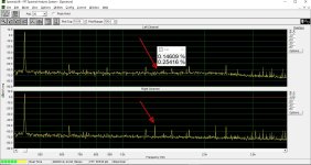
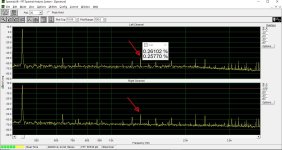
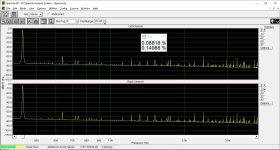
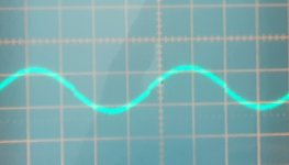
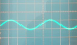
Left channel (top) adjusted for minimum THD, compared to unadjusted. Right channel (bottom) unadjusted in both graphs. Input signal: 400 Hz 6 bits, that is -60 dB sine, referred to peak 16 bits. Analog output is 3 mV peak. Scale is uncalibrated. H3 marked with arrow.
Attachments
Hi,
can you hear the difference when playing a material you know very well ? Wonder if I could hear it as I am post and half 50 y.o. -50 dB for H3 seems low enough if I am not wrong ? It affects bits precision, rigth ?
You also use ad828 as I/V which has very low noise till 2k Hz IIRC. But not so fast (slew rate and sttling time).
What I wonder is that peak we see around 630 hz, what is it ? H2 at 800 hz is flat too ! Is the peak just before H3 the next harmonic of that 630 hz peak ?
Look forward to read more about your tests. Thanks for that.")
can you hear the difference when playing a material you know very well ? Wonder if I could hear it as I am post and half 50 y.o. -50 dB for H3 seems low enough if I am not wrong ? It affects bits precision, rigth ?
You also use ad828 as I/V which has very low noise till 2k Hz IIRC. But not so fast (slew rate and sttling time).
What I wonder is that peak we see around 630 hz, what is it ? H2 at 800 hz is flat too ! Is the peak just before H3 the next harmonic of that 630 hz peak ?
Look forward to read more about your tests. Thanks for that.
Last edited:
I'd llove to have two Signetics NE5534 as buffers . (AD797 is nice too in the same spirit)... but maybe too much current noise input VS a FET !
Anyway. Where do you probe, please ? At AGND or DGND pin (same result ?) and on the DEMS decoupling pins ? That's cool, I'd like to have a spectrum analyser... too much expensive for my pocket, although I saw some handled casing ones at 150 euros but the bandwidth and bits resolution is too much low for that !
ok, will just be lurking the thread, but do remember if you can't hear it after real life checking, then....
as buffers . (AD797 is nice too in the same spirit)... but maybe too much current noise input VS a FET !Anyway. Where do you probe, please ? At AGND or DGND pin (same result ?) and on the DEMS decoupling pins ? That's cool, I'd like to have a spectrum analyser... too much expensive for my pocket, although I saw some handled casing ones at 150 euros but the bandwidth and bits resolution is too much low for that !
ok, will just be lurking the thread, but do remember if you can't hear it after real life checking, then....
Pin 5 & 14 ; according the layout pcb that links both is you have result may differ I imagine if you put the gnd probe on either. But I do not know for real.
Well I could have guessed with a 400 hz fundamental tone, I haven't readed carrefully enough. Then the result given by the operationna amplifier l could influence I surmise as you are in analog domain measurement at outpt. But can we hear it is another story maybe.
cheers
Well I could have guessed with a 400 hz fundamental tone, I haven't readed carrefully enough. Then the result given by the operationna amplifier l could influence I surmise as you are in analog domain measurement at outpt. But can we hear it is another story maybe.
cheers

Crossover distortion due to DNL is nicely depicted at the end of the article of Henk ten Pierick:
https://www.dutchaudioclassics.nl/Philips-DEM-Dynamic-Element-Matching-for-TDA1541-and-TDA1541A/
https://www.dutchaudioclassics.nl/Philips-DEM-Dynamic-Element-Matching-for-TDA1541-and-TDA1541A/
A S1 from Hollland and France plants don't sound the same as a non sorted out batch and even less the same than the chips made in Taiwann despite they share same LSB levels. One still have to test with sound how translate that won number in real life imo. Mostly to check if the studied thing has corelation with the object of the study (which itself is of course interressant on his own of course )
on the thermal thing. People mostly heatsinked their TDA1541A because it heats a little. I nevver did and never lost one TDA1541A or TDA1540 (nore 1545 or 1543) because of thermal stress. But people noticed improvment (biass ?) they heard when heatsinked. And even more if the heatsink was tied to close ground (shield ? Antenna effect different when heatsinked or not ? . EMI/EMC thing ?
Yeah, look forward your study. Also still wonder if the number change according the I/V technic or in the same tipology whatever it is, if the parts are changing (passive and also active parts).
)on the thermal thing. People mostly heatsinked their TDA1541A because it heats a little. I nevver did and never lost one TDA1541A or TDA1540 (nore 1545 or 1543) because of thermal stress. But people noticed improvment (biass ?) they heard when heatsinked. And even more if the heatsink was tied to close ground (shield ? Antenna effect different when heatsinked or not ? . EMI/EMC thing ?
Yeah, look forward your study. Also still wonder if the number change according the I/V technic or in the same tipology whatever it is, if the parts are changing (passive and also active parts).
Later regular ones 95+ are considered to be S1 grade quality, with 98 sounding quite different to the others. Which may bring quite interesting things to the table. I've been quite busy lately, hardly have time to listen to music, let alone design something, but this may be worth the effort to put on an experimental tda dac pcb when time allows.Unfortunately not. I have another one from the same batch (HSH8731 1Y) and an R1 grade.
I suspect an S1 would need less correction, an R1 would need more.
Thermal stability is the next thing I have to study.
Yes, I tried that experiment with a friend about a decade ago with a spare NOS TDA1541A S1 from holland, vs a late-production non-S1 from taiwan.
There was nothing in it, in measurement (Inc IMD) -- if anything, the late Taiwan-produced chip measured better. Which you might expect, given at that point the process was old, in a new clean fab etc.
I'd also point out, if the OP is worried about nA-level of adjustment on the Decoupling pins - just ensure the PCB is very clean and dry. If you live in a humid country with a 30+yr old pcb, I bet surface leakage is just as significant - so clean with Isopropryl alcohol first! And if the PCB is paxolin or similar - just forget it, waste of time.
This is also why using electroliyic and other 'leaky' capacitors is a very, very bad idea , for this particular usage.
- Home
- Source & Line
- Digital Line Level
- TDA1541A reducing DNL