I purchased a non-working Russound P75 amplifier with two TDA7294 chips.
Background -
When I got it only one chip was burned, so I took it out of circuit and tested the other chip. Apparently it was close to durning up too, because after a couple minutes of "light" use it went up in a blaze of glory and sparks galore!
So off to Mouser to order a couple more.
While I was waiting for the parts, I took out the chips and tested all the resistors and voltages (w and w/o a DBT in series) to make sure I was getting the right voltages to all the parts (IC's, and Chips).
To my surprise everything seemed in order and only the chips were damaged.
Fast-forward to the parts coming in - I replaced the TDA7294's, checked all my solder under a 20x magnifying glass and ran it with the DBT again. It all checked out with 0.9-1.2mv on the speakers (R/L both A and B) and has been playing music for 2 days now, with no known issues - except HEAT!
My Questions -
1) There are two large 220r 5W (I think) resistors that get very HOT!!! The +VCC one gets up to 140-dgrees F hot (R201 - left one), where the -VCC one only gets to 120-degrees F (R202-right one). I know these are "burning" off voltage to get down to ~15vDC for the relay, op-amps and led. But it that amount a heat normal? Seems very hot, can't touch them after 1-2 minutes of being on for more than an instant or you will get burned.
2) There are 4-zener diodes (2 marked 18V and 2 marked 15V - see pics) but all 4 are 15V zeners. Also appear to be 5W versions. The 2 on the positve side +VCC (ZD201 & ZD203) run at that same 130-140-degree F, where the -VCC ones run about 100-degrees (ZD202 & ZD204) after the same amount of time. The two caps between the zeners also measure hotter on the Positive side.
3) Is anything going to burn-out because of this "heat", or is it just the design of the amplifier and "made" to run like this.
Is there anything I should check, that might be faulty, that would increase these temperatures?
Attachments


Designer used 5W parts because he *expects* them to dissipate close to that, certainly above 2 or 3W in normal operation.
Just did a little Math:
Don´t know your power rails but if they are +/-40V , each resistor is dissipating (40-15)squared/220: 2.8W ... right what I assumed.
If rails are higher they´ll dissipate more.
And any small part dissipating 3W or more will run HOT.
Just did a little Math:
Don´t know your power rails but if they are +/-40V , each resistor is dissipating (40-15)squared/220: 2.8W ... right what I assumed.
If rails are higher they´ll dissipate more.
And any small part dissipating 3W or more will run HOT.
I don't think the 7294 problem wont be anything to with the hot resistors unless the y are very close to the 7294's.
Can you show a picture of the heatsink arrangement.
If the 7294's are burning up then it could be the heatsinks is too small.
The 7294 is fussy about layout and the feedback resistor needs to have as short a path as possible.
Also you musn't have too low a gain on the 7294, I think 22 is the minimum or the 7294 will become unstable and oscillate and burn up. Its worth looking for oscillation on the outputs.
Thanks for showing the math. You are spot on 39V rails so it looks like there is enough “head-room” with 5w parts.
Thanks for confirming - it does appear within designed specs.
Thanks for confirming - it does appear within designed specs.
...220r 5W (I think) resistors that get very HOT!!! ...140-dgrees F hot ...
For some reason, electronic work is done in un-American degrees. You say 60 degrees C.
If the room is 60C, then there's no self-heat at all. (YOU may be sweaty.) More likely the room is near 25C. Then the Temperature RISE is 35 degrees C.
This link is not your resistor, but resistors is resistors. The 5 Watt model is rated for 170C rise at 100% load and room below 35C. However there is a 155C limit on rise for this product line.
35/155, the resistor appears to be working about 1/4th of the rise which is allowed.
Power resistors do run HOT. The whole point is it waste-off power, heat. The cost is roughly related to how much stuff is in them. Big watts, small body, HOT! Carbon, metals, ceramics can run VERY VERY hot for quite some time. Red hot, white hot. Hot enough to set fires. Also hot enough to fail from oxidation. But the typical MAX rating is often HOT enough to brand the brand-name in your finger.
Your resistors appear to be within rating. However I do not like the toast on the PCB. We see this often on Fenders which come in half-dead, because the low-volt supply has cooked the joints and they fail in a decade or two. It may be an option to move all the hot parts off to a substantial tag-strip mounted in a corner with ample air flow.
...5W (I think) resistors that get very HOT!!!....
Attachments

Thanks for the replies/information PRR, good stuff to know.
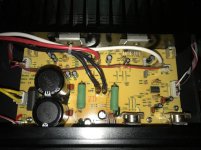
Tried to post some better pictures, in case someone else needs them. You can't quite see all four of the zener diodes (very bottom edge of PCB, below the Green 5W resistor).
I also took some more "industry standard" temperature readings.
Ambient - 65F (18C)
Resistor Temps - +VCC 143F (60C), -VCC 130 (54C)
Rise of Ambient - 80F (27C), 65F (18C)
Similar for the 5W zener diodes, but they are charring the board, because they were not installed with any space between them and the board. Might be able to help that by installing new ones, but leaving them 2 mm off the board.
If I place an order - might just get 2 7W resistors to lower those temps a little too.
Attachments

Last edited:
I opened up a Audiosource Amp100 I have and those "power bleeder" resisitors are 330r and 3 watt.
Using the calculation above, if I changed them to 330r, they would dissipate 1.9 watts, instead of 2.84 watts (current 220r).
Is that an option - or will changing the resistance have a negative effect on the circuit?
I'm new to this - so I'm asking to get a better understanding of the circuit. Seems they are really only there to bleed off voltage from 40 to 15, so changing the value would have little detriment, but wanted to ask first.
- Status
- Not open for further replies.
- Home
- Amplifiers
- Chip Amps
- TDA7294 Russound P75 amp question about HEAT