Hi, got one of these to play with from good old eBay.
On internal inspection on the main board R436 is cooked which feeds +45v to the front panel PCB. 47 Ohm.
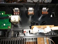
Getting the front panel PCB off was a challenge as the three rotary knobs would not pull off!
Could someone have glued them on? Volume knob pulled off with normal effort.
Anyway, unsoldered the three pots and got the board off that way.
R704 is cooked which feeds the -15.88v regulator. I was expecting damage to the plus volt supply.
According to the service manual R703 and R704 are 820 ohms but in my one R703 is 10 ohms in value.
Which is the correct value and any thoughts on what would fry those resistors.
All the regulator transistors seem fine.
Many thanks.
On internal inspection on the main board R436 is cooked which feeds +45v to the front panel PCB. 47 Ohm.
Getting the front panel PCB off was a challenge as the three rotary knobs would not pull off!
Could someone have glued them on? Volume knob pulled off with normal effort.
Anyway, unsoldered the three pots and got the board off that way.
R704 is cooked which feeds the -15.88v regulator. I was expecting damage to the plus volt supply.
According to the service manual R703 and R704 are 820 ohms but in my one R703 is 10 ohms in value.
Which is the correct value and any thoughts on what would fry those resistors.
All the regulator transistors seem fine.
Many thanks.
Further investigation and looking at the circuit diagram which spreads over two pages I suspect the AN7062N as it is one of four items that uses the -15v supply and a direct connection to the +45v feed.
I have a AN7062N somewhere and will try it with some new fusible resistors via my dim lamp.
I have a AN7062N somewhere and will try it with some new fusible resistors via my dim lamp.
Looking at the circuits for the SU-V45A , 55A and 65A all three models use different circuits to provide the plus and minus 15v rails so no confirmation of the correct resistor value.
To test, I have replaced the chip AN7062N and fitted 470R resistors in location R703 and R704.
Powered up with half the front missing (no indicators or speaker switches) and it at least now operates the protection relay.
Just not sure about those resistors and also need to replace the 47R on the main board which still works but looks cooked.