I just got a Tek 576 curve tracer for nothing. I saw it, so beautiful, I just couldn't let it go, even if for my level of expertise and for my needs (or, should I say, desires), it's way too much. I Got it home, checked the inside for obvious problems, it's surprisingly clean and, looking at the knobs and switches it doesn't seem to have had any serious use, if any use at all.
I turned it on, and no magic smoke, all good, apart from the position of the cursor, which can't be zeroed properly and keeps jumping all over the place (mostly vertically).
Does anyone have any ideas about the reasons?
Here is a video showing what happens.
I turned it on, and no magic smoke, all good, apart from the position of the cursor, which can't be zeroed properly and keeps jumping all over the place (mostly vertically).
Does anyone have any ideas about the reasons?
Here is a video showing what happens.
I have repaired a number of Tek curve tracers over the years, both the 576 and 577 and the old 570 of which I own two. The vertical amplifier in yours is drifting. The most common cause of this is dirty controls, especially the push buttons. I'd start by cleaning the push button switches. Try working them in and out first to help clean them. The ones in the middle of the front panel are tough to reach but can be reached from the bottom. Lay the tracer on it's side and remove the bottom plate. When using a spray can of cleaner you will need to make an extended spray pipe by splicing two (or more) together with heat shrink tubing.
If you don't have a service manual, by all means get one. Either a hard copy or a CD with PDF files. Ebay or places like "Manuals Plus" sometimes have hard copies. Since it appears to be working the power supplies are probably good. But you should check them anyway at their test points on the side of the rear regulator board. (see below) Also pull out and reinstall the test fixture to make sure the contacts on the "blue ribbon" connectors are clean. And make sure the test fixture rotory switch is in the twelve o'clock position.
Power supply test points: (indicated on board & referenced to ground)
Pin E +100V
Pin F +12.5V
Pin I -12.5V
Pin K -75V
Pin M - ground
Pin Q +5V
Pin U +4.5V
Pin Z +15V
The "Display Invert" button is usually the one causing problems on the one here. Some of these front panel buttons control plug-in relays inside. You will hear the relay clicking when pressing the button typically. If you hear the clicking, then its the relay contacts that are causing the problem (if that is what is affecting the problem), not the switch. I just keep pressing the button repeatedly until the problem clears up. But it will likely return the next time it is turned on. I guess one could replace the relay if you can find a replacement. Or try disassembling the relay to clean the contacts.
The rotary front panel switches use rotary cams to operate rows of tiny gold contacts, actually on the PC boards. These do not have contact wiping actions, so the slightest dust that gets into one will stop it working. Can be cleaned with air pressure or a dust remover spray can after removing the cover over the switch cam.
The tiny PC board contacts, under the rotary cams that control the light bulbs for the scale factor readouts, draw enough current thru the PC board contacts to eventually erode away the foil. These can be fixed by bending the contacts carefully to hit the board foils in a slightly different location.
.
If you plan on using the 576 for tube curve tracing, some mods will be needed.
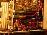
The "grid" (gate) voltage stepping does not have enough range for most tubes. A boost supply can be added which is switchable in series with the normal V step amplifier supply. Then the step amplifier assembly on the big aluminum heatsink (behind the step amplifier PC board) has to be replaced with HV transistors. I converted to a complementary design using MJL1302A and MJL3281A 260V transistors plus MJE15033 and MJE15032 250V drivers. (pics below) There are some 350V versions of all these available too.
Then some other parts in the step amplifier circuit need upgrading to higher voltage: CR391, CR393 changed to 600V 1 Amp. CR384, CR386 changed to UF301 3A 800V, C391 and C393 changed to 22 uF 350V.
The grid V stepping on this unit can now do a +/1 170V range, plus a fixed added V (like 50V) for grid 2 curve sets.
I also modded the collector supply switching to change the top 1500V scale to 750V (safer, and can supply higher current then for TV Sweep tube testing).
The E sense contacts on the test plug-in unit and the associated DUT toggle switch contacts were changed over to select one of two external screen voltage supplies. (so two different type tubes can be compared by just toggling the switch).
This way screen V only gets applied when a particular DUT tube is being curve traced.
Then the step generation digital circuitry got modded to do 15 steps (selectable) instead of the 10 steps standard. TEK went out of their way to limit the 4 bit counter to a count of ten. Just pull out pin 12 of IC U72 (SN7400). A D/A resistor, R64, has to be changed to 1/2 value for a 1,2,4,8 current sequence. I just put a pot across it so it could be calibrated accurately.
There are also some connections on the "blue ribbon" connector to the plug-in DUT box that provide for external Vertical and Horizontal amplifier connections, plus two sets of contacts for relay switch-over from the normal internal Vert. or Horiz. signals. These were brought out to BNC connectors on the side with toggle switches for activating them. This is useful for things like plotting screen current from either a sense resistor below the screen supply or a DC current probe source (TEK AM503 ) or a TEK P5200 HV differential probe (maybe for UL, UltraLinear, tube setups).
Last pics show some of the new capabilities being used, like 750V plate sweep, and 15 traces. Crazy Drive linear tube operation. (found using the curve tracer)
Attachments


Last edited:
Thanks for the very detailed replies.
I finally got some time to do the some cleaning of the switches and buttons, and I believe the cause was indeed the invert display button.
All that drift is now gone, and the cursor is rock stable.
I only have to find a replacement for the plastic connection between the two shafts of the looping compensation knob, which is broken, and once that is done it should be good to go.
I noticed that the traces on the screen flicker quite a lot when I test transistors, with increasing flickering with increasing number of steps displayed. Is that normal? With 10 traces it makes it quite difficult to actually measure the levels precisely.
Finally, I might try and use it in the (far) future to test tubes, at this stage I don't have a lot of use for it, and I bought it mostly in a rush given how well maintained it looked and given its price. I had thought about a curve tracer for quite some time in order to test v-fets, and this is gonna be its main use for now.
I must say, it really looks incredibly well built.
Some flickering of the trace is normal with these. It can be reduced a bit more by increasing the repetition rate by 2X. (Or normal if you're in .5 setting) Use the white button near the bottom just above the plug-in fixture. And yes they are built exceptionally well. The newer ones are less so. Looping compensation is used when doing very low level measurements to keep the traces closed by nuling out stray capacitance.
- Status
- Not open for further replies.