The Rabbit Hole Music Streamer Project
a study in persistence and problem solving
a study in persistence and problem solving
A While back my Kid showed me a Facebook posting of an awesome looking music streamer someone had built using an ultrawide but narrow display and a Raspberry pi running the Volumio software! And of course he wanted to build one!! So, we contacted the original poster, and they were kind enough to share their build details. We bought the same display and a Rpi4 and after a lot of rigmarole we got the Volumio software installed. We played around with it a bit but neither of us really liked the functionality of it. And the more I read about the issues of audio over a Raspberry pi, the more we soured on the project. We investigated the audio parts of the hardware, but our interest in the project cooled and the parts we bought are still sitting there on the shelf.
Fast Forward to a bit later, and one day I was in my shop. Stuck on a problem with a unit I was working on. I sat there staring blankly at my shelf of “I’ll get to it someday projects”. One item caught my eye. An Emotive ERC-2 cd player I bought sometime ago from somewhere, I don’t even remember where I got it from now. It had a dead unobtanium cd drive in it. But all the circuitry “looked” nice. It was a well thought out unit. Beefy power supply on the left. Discreet analog circuitry on the right. With a center section that had its own cover with sound deadening padding on the bottom of the lid to help reduce transport noise!
As I sat there pondering the issue I was working on. I started thinking…You know, a cell phone would just about cover the space where the CD drive slot is….I walked over and held my cell phono up to the faceplate and sure enough. It was about the perfect size. I pushed the project I was working on aside and put the CD player on the bench and cracked open the lid to have a look again.
And down the Rabbit hole we go.
I removed the cd drive and tossed it in the trash can. Then I started looking at the digital board. Besides the cd transport control circuitry, it had an AD1955A Dac chip. No slouch there. I got curious if I could “tap” into the circuitry just before the Dac chip and inject an I2S signal? I removed the Digital board and, on the bottom, noticed the silkscreen printing around an unpopulated connector with all the I2S signals and it had +5V, Gnd, mute and reset! Walla! Everything you would need! Hmmmmm. Gears start spinning in my head. I had originally saved it thinking that maybe I could paste in a CDpro2 transport into it and make that work somehow, but this looked ideal for the Music streamer project the kid and I had talked about.
The next time I could get the kid over to the shop, I showed him player and we started discussing what to do with it. Neither of us were thrilled with the Raspberry Pi’s so we started thinking that a small computer might fit in the middle. Something like an ITX motherboard, I looked over at another shelf and realized I had an old Lenovo Ultra Small form factor PC sitting there. It would JUST fit inside, and the padded noise reduction cover would help mask the fan noise. And I just happened to have a box of Rigisystems USB to I2S boards left over from my days at Audio Research!!! And if we ran a Windows PC then not only could it run Spotify, but it could run Foobar, Jriver or Media Monkey, Youtube or any other app Dejour! We liked the idea and while Windows is not perfect for audio. It is easier to deal with and more versatile then the Volumio/Rpi solution and easier, at least for us, to work with.
1st step was to see if we could even make the DAC work. This would determine if we would continue the project with the platform. I reverse engineered how the Dac chip was tied into the Mediatek CD control chip. And I was able to carefully cut the traces for the I2S lines to the Controller. This would allow me to inject an I2S signal from my Rigi USB to I2S board directly into the AD1955 dac chip. Little bit of solder flinging, jumper wires and duct tape, we had 44.1khz audio playing!!! This will work!!!
Further down the Rabbit hole we go.
Perusing eBay for a faster SFF PC I found these really cool computers called “NUC’s”!!! They are the size of the palm of my hand and fully blown windows PC 12gen processors, plenty of memory, M2 SSD drives and lots of IO ports!! This looked like a better solution. We decided not to go with something too new. Wanting to keep the heat and more importantly the cost down, we found a good deal on a 7th gen i5 NUC with 16gb of ram and a 256gb ssd hard drive. The smaller size would allow more room in the chassis for a better layout.
We also found a really nice High Resolution 5” touch screen HDMI display on Amazon. The size looked perfect to completely cover the CD drive Slot and still fit under the Emotive Logo for a near factory look. I am lucky enough to have access to a Machine shop at work and so I was able to carefully mill out the front panel and inset the touch screen display. Thius required a lot of fabrication creation of a way to mount the display. I machined a plate to mount inside the front panel to hold the display in place.
Then I started looking at the front panel buttons. Hmmm Play, Stop, track Forward and Track back. How could I make those work…The next morning as I sat drinking my morning caffeine mindlessly surfing the web (No doubt reading DIYAUDIO.com!). I looked down at my Dell keyboard and looked right at the “media controls”!!! Play, stop, track forward, track back, VOLUME and mute!!! HMMMMM and down we go.
Off to eBay I go and I bought the same model Dell USB keyboard. I Disassembled it, removed the small circuit board from inside the keyboard and figured out how to wire it to the front panel buttons. Walla! USB front panel controls and they work perfectly! I was able to mount the small circuit board from the keyboard to the back of the front panel circuit board with jumper wires from the switches to the board. I then added a Rotary encoder where the Eject button was on the front panel and that is now the On/Off and Volume control. I still need to work out a better-looking Knob but for now its functional.
We continued and with the front panel controls sorted out, we needed to mount the PC and work out how to deal with the Processor heat. We figured out that we could remove the outer chassis from the NUC and mount the inner chassis to the bottom near where the CD drive had been. I cut an oval hole in the bottom of the chassis and fabricated a sort of “scoop” vent to send the heat out the bottom of the CD players chassis. There was enough venting around the side of the chassis for cool air to be drawn in.
Next was what to do about the power supply? The NUC comes with a wall wart type power supply. We could not just solder wires to the plug and stuff it in there. I cut open the wall wart shell hoping I could find a way to mount the internal board from the supply somehow. I thought of 3D printing something. But decided to look at Digikey and see what they had. Lo and behold they had the same FSP brand, voltage and power rating in an open frame type power supply and at a reasonable price!! So out comes the credit card again
I found I could mount the power supply behind the front panel in place of the emotive Housekeeping supply that was no longer needed. In fact, the factory plug that went to the Emotiva housekeeping supply plugged right into the new FSP supply! Perfect! Power supply problem solved.
I then fabricated a metal plate to mount on top of the NUC to use as a way to mount the Rigi board. And this is where things went sideways and project creep set in…
In testing we found that we could get audio to play at 44.1khz, and 48khz. But we could not get anything above that to work. The AD1955 DAC chip should be capable of 192Khz!!! Reading the AD 1955 datasheet, it appears that unlike other DAC chips I have played with. The AD1955 requires you to set certain registers for certain modes. But, it can be used in a default state without a microcontroller. I dug back into the Emotiva digital board and found that the SPI control lines for the AD1955 were all tied to ground! Which the datasheets describes as the default state for applications where you only need 44.1/48khz. We would have to add some sort of controller if we wanted to do anything higher then 48khz. And that would require some micro surgery on the SMD IC to somehow make that work. Meh, we decided that 44.1/48khz would be fine….for now…more to come on this subject later.
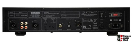
The Emotiva ERC-2 CD player has some nice Digital output options. RCA SPDIF, Toslink and XLR AES/EBU outputs. Those are all fed from a separate output on the Mediatek CD controller IC. We would need a SPDIF output from the Rigi USB to I2S board to make that work. And this is where things took a left turn.
The Rigi Systems USB to I2S Board is capable in factory trim of 8 channels of 192khz audio In, 8 channels out, SPDIF In and Out and Midi In, Out and Through!!! BUT…as the boards I have are from Audio Research, they have a limited functionality driver. Rigi Systems is now out of business and there is no recourse for doing anything with these boards, except with the ARC drivers. Plus they don’t work well with Windows 10/11. They are now…outdated. ARC in fact has updated their USB/I2S solution a couple of times now from these old boards. But I had a pile of them and wanted to find a use for them and I thought this might be perfect. I tried my best to hack the Gibson, but my hacker skills are just not that great and nothing I did would make the SPDIF output work. I reached out to Theysecon the company that wrote the driver for Rigi Systems and well…they were less then accommodating. Simply stating “talk to the manufacturer”. So, we took a step back and discussed what we wanted to do. And we both figured, why not make it the best we can make it? We have come this far.
Down the rabbit hole further yet.
After a lot of googling. It seems that the JLsounds USB to I2S board was our best option. It has many great reviews, Helpful customer service and Works with win10/11 and will output I2S AND Spdif at the same time. Out comes the credit card yet again and a short time later the board arrives.
What a nice little board! It took a couple of emails to the maker to fully understand how to configure the board. But they answered all my questions, and we got it to work perfectly. Then some more micro surgery and I was able to tap in and send a SPDIF signal the digital output section and got all the digital output ports to work! we figured that at least the digital outputs can work up to 192khz even if we couldn’t get the internal AD1955 DAC section to work past 48khz.
Of note however is that there are parts on the JLsounds board that get REALLY warm. Shouldn’t be an issue but I nabbed a couple of micro sized fans from the scrap bin at work that should help keep things under control.
And now further down the rabbit hole we go at rocket speed!
We decided to explore what it would take to get the AD1955 DAC chip to work at all frequencies. I enlisted the help of a friend of mine that has knowledge of programming Arduino micro controllers. Showed him the data sheets and asked if he could write a program that would look at the word clock line coming from the JLsounds board, and send the required commands to the AD1955 DAC chip to set the registers to work at whatever sampling frequency was coming in. But we started looking at the JLsounds USB to I2S board and realized they have 4 output pins that have binary information on them related to the sample rate. We can just use those 4 pins instead of having to count the word clock line. Which made for a much easier code.
I removed the Digital board from the player and I was able to carefully desolder the 3 control pins on the AD1955 DAC chip, and lift them slightly from the board and slide a piece of Kapton tape under them insulating them from the ground trace below. I was then able to solder some short pieces of kynar wire to each control pin. I took a piece of perf board and soldered a 6 pin header on it and super glued it down the Digital board. I attached each of the 3 control wires to a pin and grounded the other 3 pins. This would allow me to place a 2 pin jumper on each line and continue to work with the unit while the code was being written or give me a default should the code not work etc.
I found the smallest Arduino board I could find that had enough I/O pins. I settled on a Pro Micro board. This has a Micro USB port on it so it can be powered easily by the NUC and we can use the NUC to program the board if we need to make changes later on without having to open the unit. And here is where we ran into some issues. 1- I needed to a way to mount the Pro Micro board as it is designed to plug into a breadboard and has no other way of mounting. We also discovered that for whatever reason. The makers decided not to break out the SS line to a pin on the board making SPI communication difficult. So, I fired up the old PC and cracked open the EagleCAD and designed up a quick adapter board, fired off the Gerbers to SEEED studio Fusion and a week later I have a way to mount the pro Micro and have the SS pin brought out to a header. Problems solved. My friend code the code finished just in time and with a little prodding, poking, experimenting and refining we now have a working DAC that will output anything from 44.1khz to 192khz!
BUT there is MORE!!!!
20,000 feet below the surface of the Rabbit hole now, we started talking and thinking….HMMM it would be nice to be able to output HDMI to a TV and have some external USB ports so we could plug in an external hard drive, keyboard and mouse etc…..YEAH!
The NUC is cool in that is has built in Bluetooth that will work for a BT keyboard and Mouse. But we found that with the covers on, the Bluetooth and Wifi had limited range due to it being inside the metal CD player chassis. More googling and we found a place sells NUC’s and NUC accessories. We found a set of remote mount Wifi Antennas that we mounted on the back of the unit with long cables we could connect to the NUC’s internal WIFI card. And more googling I was able to find a cool little USB-C “dock” of sorts. It has an HDMI port and 3x USB ports. I machined the back panel near the top and fabricated a bracket to hold the circuit board from inside the dock to the rear panel. Allowing use of a 2nd monitor aka TV and the 3x USB ports externally! The plan was all coming together nicely…..THEN DISASTER STRUCK!!!
GOT TOO FANCY. Oops!
In my younger years, I built a lot of custom computers. Sometimes I would get fancy and change the PC’s boot splash screen to something else. My logo or an Anime character etc. depending on the client. So, I thought it would be cool to flash the EMOTIVA logo to the NUC to make it look more integrated. Which worked! Worked great! But…. One day sometime after that, I went to do some testing and found the Dock no longer worked. The HDMI didn’t work and neither did any of the USB ports. The ports still had power. I could charge my phone etc but no matter what you plugged in, windows never saw it. I removed the dock and tested it with another PC and the dock itself worked fine. But the USB-C port on the NUC had DIED! Ughhhhhh. Not sure how or why it died. But I suspect the BIOS update I did while I was flashing the Image killed it. Oh noooo. Could I have flashed the wrong bios?? Not sure. I removed the NUC and worked on it for 2 weeks and no matter what I did, I could not make the USB-C port work again. And I could not revert the BIOS back to the old version. So…Back to eBay, crack open the wallet, whip out the ol credit card…AGAIN and a week later another NUC the exact same model showed up. Thankfully it had the OLD bios version. I took a chance and re flashed the splash screen logo WITHOUT updating the bios and the USB-C port continued to work. Let me tell you, I was puckered trying that again! I will NOT be updating the bios to a new version. Should have left well enough alone the first time LOL!
Last we added a 2.5” 1TB SSD inside for storage. www.GORIGHT.com the place that had the other NUC accessories also had a cable kit that would allow you to connect a SATA device to the NUC’s internal ports. So, we were able to add a 1TB drive internally as well just to put the icing on the cake and the cherry on the Sunday! Wheeeeew that was a lot of work! And a lot of problems, but we persisted, and it was a great learning experience for the kid! With each new problem we found a way to work through it. As you do when working on any sort of project! Especially a custom audio project. And trying to convert one product into something it totally was not designed to be, has its own set of problems for sure. We are pretty happy with the results! At first glance it looks totally factory! The product Emotiva never made. And it sounds pretty good too!
Attachments
-
 20250212_202520.jpg504.1 KB · Views: 57
 -
 20250212_202418.jpg602 KB · Views: 55
 -
 4555004-617e0fd6-emotiva-erc-2-cd-player.jpg154.2 KB · Views: 55
 -
 20250212_202422.jpg614.4 KB · Views: 53
 -
 1164454-333c7936-emotiva-erc2-cd-player.jpg135.2 KB · Views: 51
 -
 20240808_191340.jpg762.5 KB · Views: 53
 -
 20240808_193844.jpg427.1 KB · Views: 48
 -
 20250212_174515.jpg531.5 KB · Views: 50
 -
 1139331-27fc5096-emotiva-erc2-cd-player.jpg22 KB · Views: 53

Hi, keep an eye on the Intel website. If USB-C got disabled by a BIOS error they are usually quick in bringing out a new version as the idea was that the update should improve stuff. I recall such an event with a NUC I had.
Also reset the BIOS to factory settings after a BIOS update.
Cool project!
Also reset the BIOS to factory settings after a BIOS update.
Cool project!