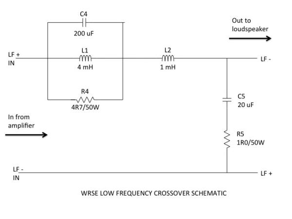
What is the purpose of a low value resistor wired in parallel in a second order low pass crossover for a woofer?So the circuit uses an inductor in series and a 200uF cap and then 3 ohm resistor in series .
Is this purely for attenuation or more complex reasons?A damping resistor?
Is this purely for attenuation or more complex reasons?A damping resistor?
Dig up your favourite crossover simulator and simulate it 😉
Anything goes for passive crossovers for hammering the response into shape. If I understand you correctly about how the resistor is placed, indeed it's used to dampen the resonance of the low pass filter, around the cut off frequency. It alters the response a bit, sometimes in a good way.
Anything goes for passive crossovers for hammering the response into shape. If I understand you correctly about how the resistor is placed, indeed it's used to dampen the resonance of the low pass filter, around the cut off frequency. It alters the response a bit, sometimes in a good way.
Last edited:
Here is an example-
What is the purpose of a low value resistor like R5 ?In my case it is a 3 ohm..
https://positive-feedback.com/Issue70/images/59%20WRSE%20LF%20XO%20Diagram.jpg
What is the purpose of a low value resistor like R5 ?In my case it is a 3 ohm..
https://positive-feedback.com/Issue70/images/59%20WRSE%20LF%20XO%20Diagram.jpg
Last edited:
Hi !
You should grab XSim - You can see these effects yourself.
In this case, the circuit takes advantage of one feature of parallel resistance/impedance:
The effective impedance is equal to or less than the lowest value in parallel. So, this means that the total impedance of the circuit cannot increase above 4.7 Ohms. The capacitor and inductor are high and low pass paths around the resistor. At very high frequencies, and very low frequencies, the impedance of the 3 parts is effectively zero. In between it will rise to 4.7 Ohms.
Grab XSim and try this circuit out with an ideal driver then try removing R4.
The 3 element parallel LCR is called a trap. It can work as a notch, here at about 200Hz. Why? I have no idea why you would want one there. 😕
This looks like a 4 ohm circuit rolling off at about 2kHz. The 1R damping resistor does usually just stop a little peak at crossover. Or you fit an electrolytic capacitor, which has a built in ESR resistance about 1 ohm.
But a strange circuit.
This looks like a 4 ohm circuit rolling off at about 2kHz. The 1R damping resistor does usually just stop a little peak at crossover. Or you fit an electrolytic capacitor, which has a built in ESR resistance about 1 ohm.
But a strange circuit.
Oh, sorry, completely misread the question! R5 does affect phase, like Radule states, but it also affects the impedance of the system as a hole.
In second order filters (high or low pass) you'll often see a resistor in series with the second pole. It's often just enough to prevent the impedance from collapsing, and what's weird, you may not see the effect in the section the resistor is in. 🙂
For instance, this resistor may keep the impedance below the crossover point higher than otherwise.
If you have a very beefy solid state amplifier, this wont matter, but with an average SS amp or a tube amp, this can actually cause an audible depression.
Along similar notes, people willy-nilly replacing caps and coils in shunts don't take into consideration inherent DCR or ESR, and are often surprised how crappy the result sounds. 🙂
Best,
E
Thanks for the answers/speculation.
Whatever they are I do not like what they do to the sound.
The speaker kit I am building uses two of them -one on the woofer and another on the midrange.I much prefer the sound with them removed from the circuit.They seem to flatten the sound and rob the music of vibrancy and dynamics.
Whatever they are I do not like what they do to the sound.
The speaker kit I am building uses two of them -one on the woofer and another on the midrange.I much prefer the sound with them removed from the circuit.They seem to flatten the sound and rob the music of vibrancy and dynamics.
Why the mystery. Of course we are speculating.
This is a terrific use of a trap that works well with 5" and 8" basses.
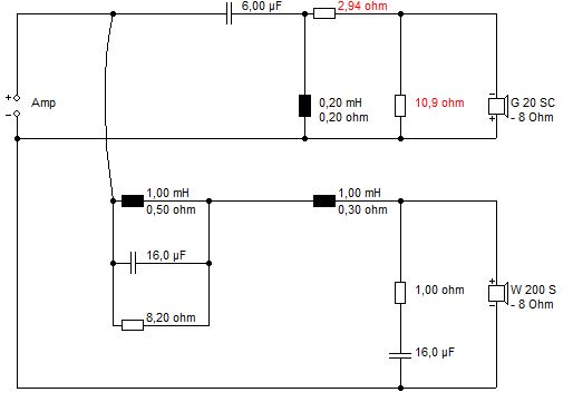
One of the most useful circuits in the repertoire. In practise, you might use a NP electrolytic in the 16uF shunt. Comes with 1R resistor built in. 😀
This is a terrific use of a trap that works well with 5" and 8" basses.
One of the most useful circuits in the repertoire. In practise, you might use a NP electrolytic in the 16uF shunt. Comes with 1R resistor built in. 😀
I find this comment interesting-
In my experience of tinkering with speaker crossovers, I get the crossover frequency and phase as correct as possible for the exact crossover point relative to what the overall impedance is at that point, and don't try to get an exact 12dB slope beyond that. When I've experimented with adding components such as a zobel network, the lines look better on the simulator, but it has always actually sounded worse to me. Getting the frequency and phase correct at the crossover point is by far and away the most important part of a crossover, and adding more reactive components only serves to worsen the sound in my experience.
In my experience of tinkering with speaker crossovers, I get the crossover frequency and phase as correct as possible for the exact crossover point relative to what the overall impedance is at that point, and don't try to get an exact 12dB slope beyond that. When I've experimented with adding components such as a zobel network, the lines look better on the simulator, but it has always actually sounded worse to me. Getting the frequency and phase correct at the crossover point is by far and away the most important part of a crossover, and adding more reactive components only serves to worsen the sound in my experience.
Thanks for the answers/speculation.
Whatever they are I do not like what they do to the sound.
The speaker kit I am building uses two of them -one on the woofer and another on the midrange.I much prefer the sound with them removed from the circuit.They seem to flatten the sound and rob the music of vibrancy and dynamics.
Try replacing with Mills, I'd be curious if the issue is the R quality. I doubt it.
What I suspect is happening is you are getting a dip in frequency response you find pleasant.
Best,
E
Just the opposite, Erik. The damping resistors he wants to remove are more to dip the response. He likes it without them.
Later,
Wolf
Later,
Wolf
All a bit of a waste of time, IMO. You haven't told us what the drivers are.
Every combination has its own issues if you want a good sound, and simpler is not always better if there is a glaring problem that needs attention.
It's usually time-alignment, bafflestep and shouty or peaky or high inductance drivers that wrecks the simple theory. Otherwise we'd just use online calculators.
Wolf:
It does in this section, but the impedance can be felt in the next driver down, so in combination you can have a rise here, and a dip in the mid-woofer (assuming a 2-way). This dip won't appear in a simulator which assumes an amp with zero output impedance btw! 🙂 But I've experienced it and read about it from a couple of users.
These sorts of dips and rises are often euphonic (i.e. not very realistic).
To properly analyze the total effect of removing this 1 Ohm R you need to know the whole system's electrical characteristics, not just the tweeters.
Best,
Erik
Last edited:
Huh? The 1 ohm resistor dampens the resonance of L2 and C5 i.e. it reduces the Q of the 2nd order lowpass filter that they form. It has the effect of lowering the level at the corner frequency without affecting things a whole lot everywhere else. Wolf is right - even without knowing knowing anything else about the system, we know that removing the resistor will peak the response at the corner frequency of the filter. If the system was designed flat with that resistor in place, removing it will make the response non-flat.
It will have an effect no matter what the impedance of the amplifier is, see below (I would hope your amplifier has an output impedance a damn sight better than 10ohm 🙂)


It will have an effect no matter what the impedance of the amplifier is, see below (I would hope your amplifier has an output impedance a damn sight better than 10ohm 🙂)
But is the cure worse than the problem?Huh? The 1 ohm resistor dampens the resonance of L2 and C5 i.e. it reduces the Q of the 2nd order lowpass filter that they form. It has the effect of lowering the level at the corner frequency without affecting things a whole lot everywhere else. Wolf is right - even without knowing knowing anything else about the system, we know that removing the resistor will peak the response at the corner frequency of the filter. If the system was designed flat with that resistor in place, removing it will make the response non-flat.
It will have an effect no matter what the impedance of the amplifier is, see below (I would hope your amplifier has an output impedance a damn sight better than 10ohm 🙂)
I understand the need for designers to get things measuring perfectly but really do wonder if that is often at the cost of sound quality.
I have owned plenty of speakers that measure really well but sound terrible and some that measure imperfectly but sound excellent-classic Tannoys and Gale 401s for example.
I'm too tired to find a good example, but examine the impedance curve of a complete system. 🙂
Or just ignore me, that's fine.
Best,
Erik
Or just ignore me, that's fine.
Best,
Erik
This is just a wandering aimless thread lacking in specifics. 😱But is the cure worse than the problem?
I understand the need for designers to get things measuring perfectly but really do wonder if that is often at the cost of sound quality.
I have owned plenty of speakers that measure really well but sound terrible and some that measure imperfectly but sound excellent-classic Tannoys and Gale 401s for example.
Speakers are a mature technology. Everything we do, bar DSP, has been known about for 50 years. You are wrong about measurement. All good speakers measure well on frequency response. Any discrepancy, even just 2dB has an annoying "Here I Am!" quality in a driver or crossover.
Other qualities that are definitely good are even dispersion, flattish power response, easy impedance, low distortion and good dynamics. The worst variable is room acoustics and the whole bass/bafflestep issue.
This 8" speaker gets very little love here. But it actually is a classic affordable design with its roots in the old Acoustic Research speakers that changed the HiFi game:
I use quite complex crossover with that one, but it's OK on simple.
Tony Gee has done a take on it that sets out to lose all resistors in the crossover: Humble Homemade Hifi - Twenty Five
John Devore claimed he didn't use resistors either, though I'm not sure I believe him.
You always take a beating with some aspect of a design. The trick must be to get everything else right. One thing you always notice about a good speaker is it sounds kind of quiet. Which leads you to turn it up very loud and annoy the neighbours. Because it sounds sweet.

- Status
- Not open for further replies.
- Home
- Loudspeakers
- Multi-Way
- The role of parallel resistors?