I am slowly warming up to some design using transistors and am trying to understand the purpose of R1 in this figure of a Darlington pair:
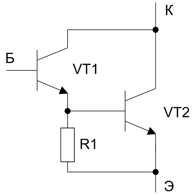
Sometimes I see the Darlington pair drawn with R1 and sometimes not. Does the presence of this resistance change the performance of the Darlington or can it be omitted?
Sometimes I see the Darlington pair drawn with R1 and sometimes not. Does the presence of this resistance change the performance of the Darlington or can it be omitted?
Without the resistor, the darlington gives a much higher current gain than the single transistor, but the transconductance of the composite is cut in half vs the single bjt and the high frequency performance is severely, almost fatally, compromised by a factor like the current gain of the second transistor.
This is because the transconductance and frequency response are both heavily dependent on collector current, which is much lower in the first transistor.
The resistor biases up the first transistor to speed it up and raise its transconductance.
( transconductance is the small signal ratio of ( delta I_c ) / ( delta V_be ). )
Eric
So, if turn-off time is not critical, can the resistor be omitted?
Would the turn off response time show up in a SPICE sim of a circuit that uses the transistors? I could just check it that way...
Would the turn off response time show up in a SPICE sim of a circuit that uses the transistors? I could just check it that way...
So, if turn-off time is not critical, can the resistor be omitted?
Would the turn off response time show up in a SPICE sim of a circuit that uses the transistors? I could just check it that way...
It depends entirely on the intended application but generally including a resistor is good practice. That said, some specific circuits would not use one but saying that I'm not thinking of audio applications. Try it in simulation, it certainly should show up because its a very real effect.
So, if turn-off time is not critical, can the resistor be omitted?
Would the turn off response time show up in a SPICE sim of a circuit that uses the transistors? I could just check it that way...
If this is a linear application there is no "turn-off" 😱
If a switch (but why? who needs that gain in a switch?) then yes. Or maybe.
So, for linear, we do need an R, else the first transistor maybe operating at a very low Ic.
Like most engineering, its a compromise.
Here is the application:
http://www.diyaudio.com/forums/power-supplies/246118-capacitance-multiplier-over-voltage-protection.html#post3709568
Look for the BD139/TIP3055 and BD140/TIP2955 in Darlington configuration.
http://www.diyaudio.com/forums/power-supplies/246118-capacitance-multiplier-over-voltage-protection.html#post3709568
Look for the BD139/TIP3055 and BD140/TIP2955 in Darlington configuration.
I probably would add something like a 1k in that application. Another practical issue could be the rating of the BD139/140 and the maximum allowable collector current. Something like TIP41C/42C might be more appropriate.
I probably would add something like a 1k in that application. Another practical issue could be the rating of the BD139/140 and the maximum allowable collector current. Something like TIP41C/42C might be more appropriate.
Although I didn't post an updated schematic I changed the driving (first) transistor from BD139/BD140 to 2N4401/2N4403 and am using TIP35C/TIP36C as the second (power) transistor.
In my sims I see the first transistor current not exceeding a few tens of milliamps peak. I happen to have the 2N devices on hand and they are rated to 600mA. The BD139/BD140 were overkill. Vin and Vout are always within a few volts of each other, unlike in a power amp.
Regarding turn off time, the fastest transient that the transistor will be dealing with is 120Hz ripple - nothing very fast at all. I don't see any effect whether the resistor is in the circuit or omitted. I was using a value of 220R-470R.
You are confusing signal rise/fall time with turn-off time, I think.
Turn off time, roughly, is how the transistor comes out of its switched on state (ie saturated) to a linear or switched off (no base current ) state.
This is NOT a switching application - the transistors are on all the time after initial switch on.
Linear parameters apply, not switching.
Turn off time, roughly, is how the transistor comes out of its switched on state (ie saturated) to a linear or switched off (no base current ) state.
This is NOT a switching application - the transistors are on all the time after initial switch on.
Linear parameters apply, not switching.
Although I didn't post an updated schematic I changed the driving (first) transistor from BD139/BD140 to 2N4401/2N4403 and am using TIP35C/TIP36C as the second (power) transistor.
In my sims I see the first transistor current not exceeding a few tens of milliamps peak. I happen to have the 2N devices on hand and they are rated to 600mA. The BD139/BD140 were overkill. Vin and Vout are always within a few volts of each other, unlike in a power amp.
Regarding turn off time, the fastest transient that the transistor will be dealing with is 120Hz ripple - nothing very fast at all. I don't see any effect whether the resistor is in the circuit or omitted. I was using a value of 220R-470R.
You have to look at the collector current of the drivers under load. With all those paralled devices I assume it a supply of high current output. Try a pulsed load on the output (simulate it) using a FET and load resistor. You could easily need several hundred milliamps or more to drive those output devices. The 2N devices are nowhere near suitable.
You have to look at the collector current of the drivers under load. With all those paralled devices I assume it a supply of high current output. Try a pulsed load on the output (simulate it) using a FET and load resistor. You could easily need several hundred milliamps or more to drive those output devices. The 2N devices are nowhere near suitable.
I opened my simulator and checked the current into the collector and out of the emitter on the 2N4401 driving the TIP35C (2 in parallel) with a sudden load change from no load to a 10R load on each rail and back again. The total power output of the PS with the 10R load is over 600W. The current into and out of the 2N4401 peaks at about 25mA. The device is certainly capably of this. It is facing a voltage drop of just a few volts across any two terminals at any time.
Note that adding the resistor will reduce the output impedance by about half, which may be desirable.
I found this related thread on another forum:
Resistors within a Darlington transistor - Electrical Engineering Stack Exchange
So now I see that the resistor has some subtle benefits. It's like a pull-down, draining some current, preventing accidental turn on when the transistor is switching.
My application seems to have the transistor on (at least barely on) most of the time, I guess the "linear" application. The voltages are around 90V. I don't want to have to put a low R power wasting resistor in there if I don't need to. Perhaps I could use something like 50k - 100k to ground?
I'm still not really sure that it is needed in my case. But I will keep looking into it, and further opinions are welcome, since I would like to learn about it.
gents, bear in mind that darlington transistor makers put those resistors in there and you can'd do anything about it, either use it or ignore it....
I opened my simulator and checked the current into the collector and out of the emitter on the 2N4401 driving the TIP35C (2 in parallel) with a sudden load change from no load to a 10R load on each rail and back again. The total power output of the PS with the 10R load is over 600W. The current into and out of the 2N4401 peaks at about 25mA. The device is certainly capably of this. It is facing a voltage drop of just a few volts across any two terminals at any time.
I ran a quick sim too for curiosity on a darlington set up. Not the identical circuit but non the less....
Driver current was over 10 times your 25ma. Don't under estimate the operating conditions. I saw afterwards you have 70v ish rails. You need higher spec devices than the TIP's imo. They are not robust. Also simulation doesn't allow for the beta droop at high currents, in other words the gain of real devices will be lower than the sim suggests.
Attachments


charlie, are you running a motor load?
This is a power supply for a class-D amp. It's described in more detail, including the schematic (old version at least) and results of sims in post #6 of that thread.
I ran a quick sim too for curiosity on a darlington set up. Not the identical circuit but non the less....
Driver current was over 10 times your 25ma. Don't under estimate the operating conditions. I saw afterwards you have 70v ish rails. You need higher spec devices than the TIP's imo. They are not robust. Also simulation doesn't allow for the beta droop at high currents, in other words the gain of real devices will be lower than the sim suggests.
I can't say why you are getting larger currents. Maybe it is because you are simulating something that is very different that my circuit??? I have posted an updated version in the thread about the CM, post #10.
The rail voltages are not 70V. Before the capacitance multiplier the rails run about 91V. After the CM the zeners hold the rails to a maximum of 86V under no load. Under high load the rails sag depending on the current draw.
Why do I need "higher spec devices"? The device specs are not exceeded, not even close. What is the problem specifically?
Why will I get beta droop? The TIPs are spec'd for 25A max. I draw only 4A max under sudden high demand of 600W... did you look at the sims I posted in the other thread???
Last edited:
I was simulating a varying load on the rail and monitoring the driver current, which all sprouted from the question of what the "turn off" resistor did in post #1
All I can say is that if you have put the ground work in (and you suggest you have) and you are sure in your own mind that the 2N devices are suitable then you must go with your instincts.
(My instincts are that I just feel they are unsuitable. Simulation doesn't tell the whole story always. You need to measure for real and see what happens particularly under the transient conditions, start up for example when caps are charging. That first few milliseconds)
I was simulating a varying load on the rail and monitoring the driver current, which all sprouted from the question of what the "turn off" resistor did in post #1
All I can say is that if you have put the ground work in (and you suggest you have) and you are sure in your own mind that the 2N devices are suitable then you must go with your instincts.
(My instincts are that I just feel they are unsuitable. Simulation doesn't tell the whole story always. You need to measure for real and see what happens particularly under the transient conditions, start up for example when caps are charging. That first few milliseconds)
There is an integrated soft-start. I intentionally included it to limit the start up transients that might not only cause high current demands but might also cause the voltage differentials across the transistors to exceed their ratings.
I don't see any problems (via simulation) under start up or sudden high demand. The kinds of things that would like to know about are those that might come from device mismatches (the sim uses identical copies of each transistor for instance, and won't model current sharing or thermal runaway, etc.) or other things that the sim does not model.
- Status
- Not open for further replies.
- Home
- Amplifiers
- Solid State
- Transistors 101 question about 2 transistor Darlington configuration