Dear all,
My sub (JBL basspro SL) stopped working a while ago and I felt like trying to see if I can repair it myself as a challenge- I don't have much experience in repairing such boards though I meddled with designing some simple medical amplifiers (studied EE about 30 years ago)
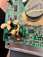
I opened the sub and removed its board and immediately saw 2 burned wires on the ferrite beads L03 and L04 in the power board (see 2 yellow markings on left of image). the schematic is attached (infinity_basslink_sm.pdf - this is the schematic for basslink sm which is what is printed on the circuit board!) and these beads appear on the 10th page (titled "CIRCUIT DIAGRAM - POWER BOARD") on the bottom left. they sit between the sinks of 2 mosfets and ground.
I tried yesterday to solder these 2 melted wires hopeful that they may have been fried during some maintenance or sloppy disconnection in the past- i reconnected the sub to the car and it worked great for a few hours!! before i left the car i tried calibrating some of the input levels and phases etc until the levels sounded well and left the car. When I started the car later that daythe sub didn't work and taking it apart again saw that the 2 wires and my soldering has melted again.
I tried checking continuity in the 2 mosfets with my Fluke in diode mode IN CIRCUIT and it seemed that the volatge differences between S/D/G are as expected (0.5 V/ no short?)
PS the transistor Q07 and an adjacent resistor seem to have hot marks on the yellow foam- see picture
Any ideas on what happened or how to proceed will be most welcome!!!!
Thanks dearly in advance,
Michael
My sub (JBL basspro SL) stopped working a while ago and I felt like trying to see if I can repair it myself as a challenge- I don't have much experience in repairing such boards though I meddled with designing some simple medical amplifiers (studied EE about 30 years ago)
I opened the sub and removed its board and immediately saw 2 burned wires on the ferrite beads L03 and L04 in the power board (see 2 yellow markings on left of image). the schematic is attached (infinity_basslink_sm.pdf - this is the schematic for basslink sm which is what is printed on the circuit board!) and these beads appear on the 10th page (titled "CIRCUIT DIAGRAM - POWER BOARD") on the bottom left. they sit between the sinks of 2 mosfets and ground.
I tried yesterday to solder these 2 melted wires hopeful that they may have been fried during some maintenance or sloppy disconnection in the past- i reconnected the sub to the car and it worked great for a few hours!! before i left the car i tried calibrating some of the input levels and phases etc until the levels sounded well and left the car. When I started the car later that daythe sub didn't work and taking it apart again saw that the 2 wires and my soldering has melted again.
I tried checking continuity in the 2 mosfets with my Fluke in diode mode IN CIRCUIT and it seemed that the volatge differences between S/D/G are as expected (0.5 V/ no short?)
PS the transistor Q07 and an adjacent resistor seem to have hot marks on the yellow foam- see picture
Any ideas on what happened or how to proceed will be most welcome!!!!
Thanks dearly in advance,
Michael
Attachments


I'm no expert, but this caught my eye and I was amazed to see you have the schematics. And they include a block diagram. Fantastic.
I would say you have a power supply problem. I would check all the components around Q07 / Q08. Start with diodes / transistors. Could be failing caps. The fact that it runs for a bit and then gets hot and fails means something isn't dead shorted or open.
I would say you have a power supply problem. I would check all the components around Q07 / Q08. Start with diodes / transistors. Could be failing caps. The fact that it runs for a bit and then gets hot and fails means something isn't dead shorted or open.

